
Search window delay tracking in code division multiple access communication systems

a communication system and code division technology, applied in the field of multi-path search processors employed in cds, can solve the problems of difficult to keep the channel impulse within the search window, noise and interference in the delay profile, and the assumption is typically wrong, so as to suppress the interference of other users and spread the bandwidth of the information data stream

Inactive Publication Date: 2006-06-06
TELEFON AB LM ERICSSON (PUBL)
View PDF12 Cites 19 Cited by
  • Summary
  • Abstract
  • Description
  • Claims
  • Application Information

AI Technical Summary

Benefits of technology

[0002]Direct sequence code division multiple access (DS-CDMA) allows signals to overlap in both time and frequency so that CDMA signals from multiple users simultaneously operate in the same frequency band or spectrum. In principle, a source information digital data stream to be transmitted is impressed upon a much higher rate data stream generated by a pseudo-random noise (PN) code generator. This combining of a higher bit rate code signal with a lower bit rate data information stream “spreads” the bandwidth of the information data stream. Accordingly, each information data stream is allocated a unique PN or spreading code (or a PN code having a unique offset in time) to produce a signal that can be separately received at a receiving station. From a received composite signal of multiple, differently coded signals, a specifically PN coded information signal is isolated and demodulated by correlating the composite signal with the specific PN spreading code associated with that specific information signal. This inverse de-spreading operation compresses the received signal to permit recovery of the original data signal and at the same time suppresses interference from other users.
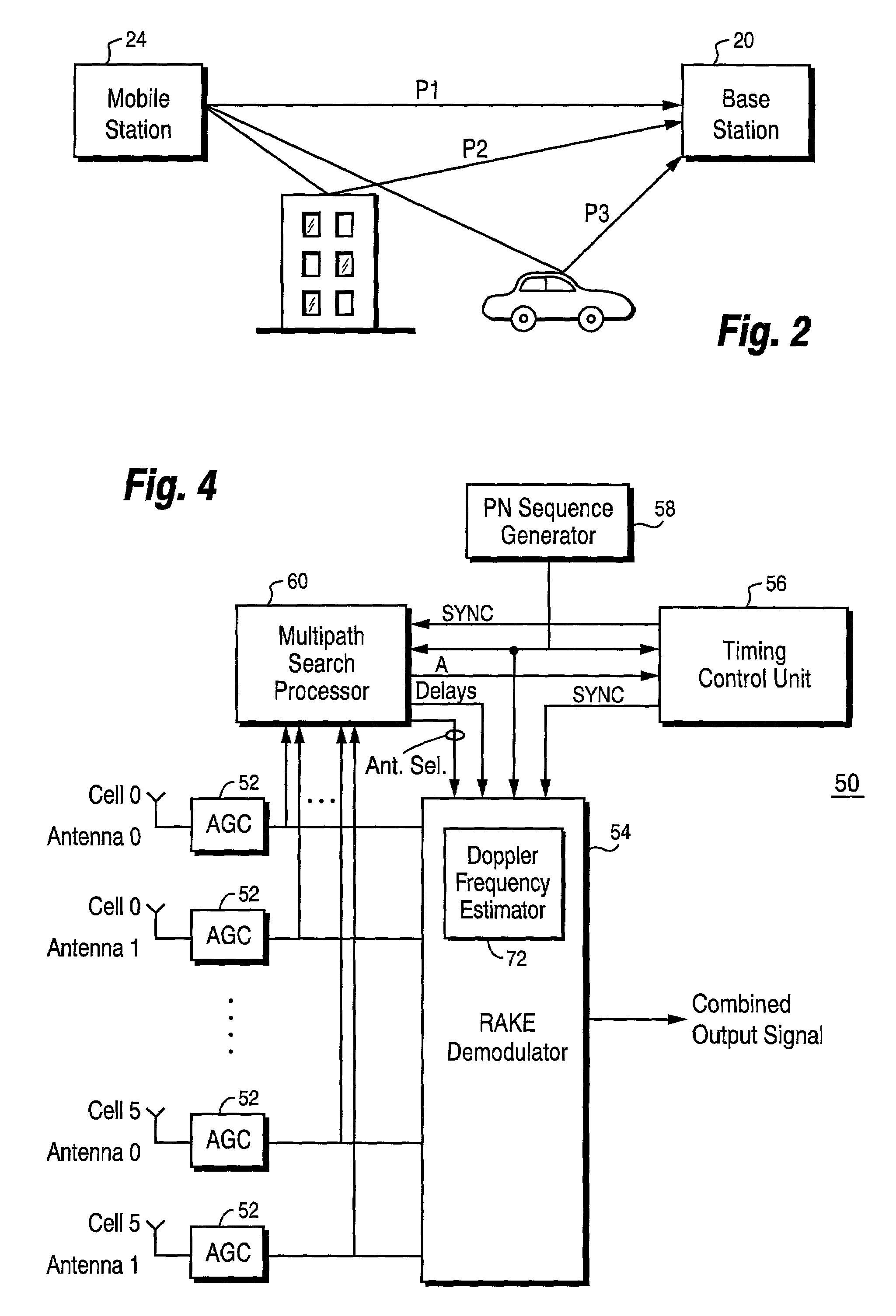
[0004]The existence of multiple paths, however, may be used to advantage in a CDMA system using signal diversity combining techniques. One advantage concerns signal fading which is a particular problem in mobile communications. Although each multipath signal may experience a fade, all of the multipaths usually do not fade simultaneously. Therefore, a diversity-combined signal output from a CDMA receiver is not adversely affected by a temporary fade of one multipath.
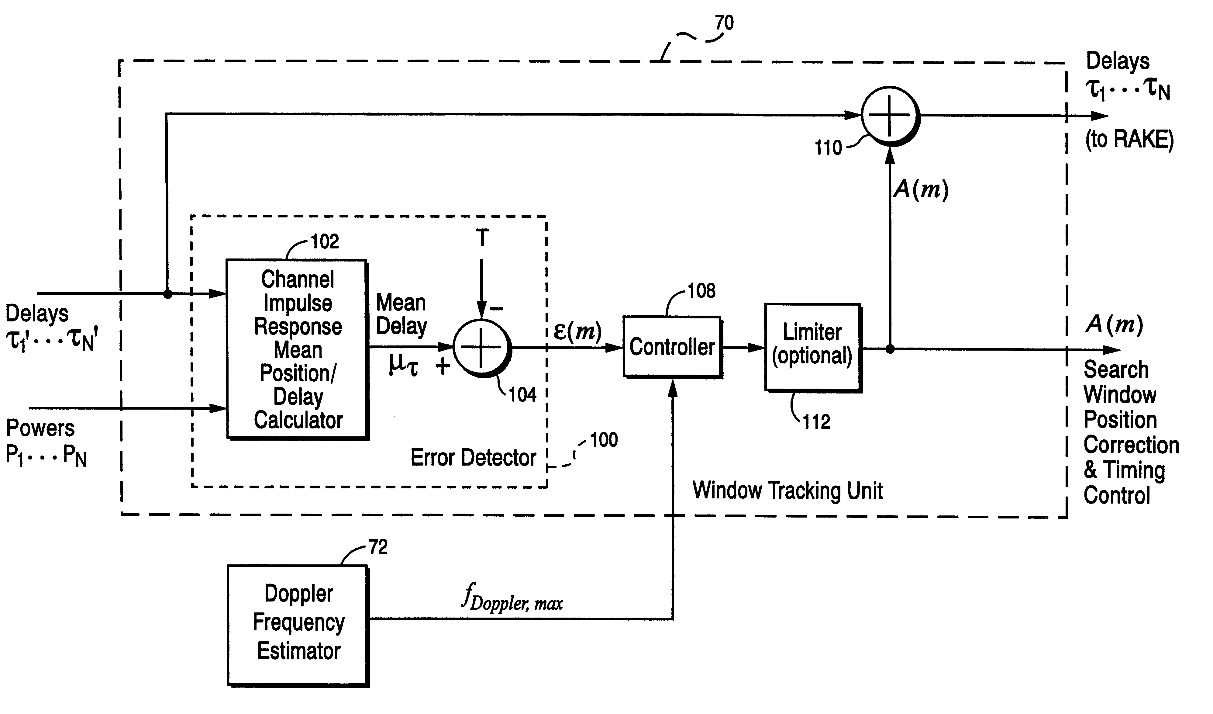
[0005]A CDMA receiver in accordance with the present invention employs a multipath search processor that searches for and identifies the strongest multipaths along with their corresponding time delays. A RAKE demodulator captures most of the received signal energy by allocating a number of parallel demodulators (called RAKE “fingers”) to the strongest multipath components of the received multipath signal as determined by the multipath search processor. The outputs of each of the RAKE fingers are diversity-combined after corresponding delay compensation to generate a “best” demodulated signal that considerably improves the quality and reliability of communications in a CDMA cellular radio communications system.
[0011]Thus, it is an object of the present invention to adapt the search window position in order to maintain accurate alignment between the estimated channel impulse response and the search window under a wide range of propagation conditions.
[0012]It is also an object of the present invention to provide a robust search window delay adjustment procedure that minimizes the influence of noise, interference, and fading, and in particular, takes into account a likelihood that faded paths may reappear.
[0015]In particular, a Doppler frequency is determined for the received signal and used to determine a maximum rate at which the search window can be moved when it is adjusted. In other words, if a path fade occurs, the search window is restricted in how fast it can shift the search window in responding to the faded path. The maximum search window shifting rate is related to the maximum Doppler frequency of the received signal. One way of implementing this is to formulate a minimum dwell time (MDT) for the search window using a maximum Doppler frequency estimate of the received signal. The MDT is the minimum time the search window should stay in its current position before being adjusted to a new position. The MDT should not be too long because the PN generators may drift to the point where a search window adjustment is necessary. However, the MDT should not be too short that an adjustment is made before a faded path will reappear. In other words, the restricted shift rate or minimum dwell time ensures that the search window tracking unit on the one hand does not correct (or overcorrect) too soon and on the other hand does not correct too late.

Problems solved by technology

The remaining received signals in the delay profile are noise and interference.
It is particularly difficult to keep the channel impulse within the search window under certain propagation conditions including, for example, slow fading conditions, e.g., 0.5 km / h–3 km / h, as well as fast fading conditions, e.g., 250 km / h–500 km / h.
Fading is a problem because when a path in the search window “disappears” because of a fade, the natural response of the WTU is to adjust the position of the search window, often significantly, assuming that the path no longer exists.
But that assumption is typically wrong because the faded path very often reappears.
If the search window is adjusted too rapidly, it may be badly misaligned when the faded path reappears.
Another area of concern is the need to use fine-tuned decision threshold(s) in search window tracking, which add to the complexity and delay of the tracking adjustment process.
In other words, if a path fade occurs, the search window is restricted in how fast it can shift the search window in responding to the faded path.
In other words, the restricted shift rate or minimum dwell time ensures that the search window tracking unit on the one hand does not correct (or overcorrect) too soon and on the other hand does not correct too late.
In addition, the adjustment amount can be limited if desired.

Method used


Image

  • Search window delay tracking in code division multiple access communication systems
  • Search window delay tracking in code division multiple access communication systems
  • Search window delay tracking in code division multiple access communication systems

Examples


Embodiment Construction

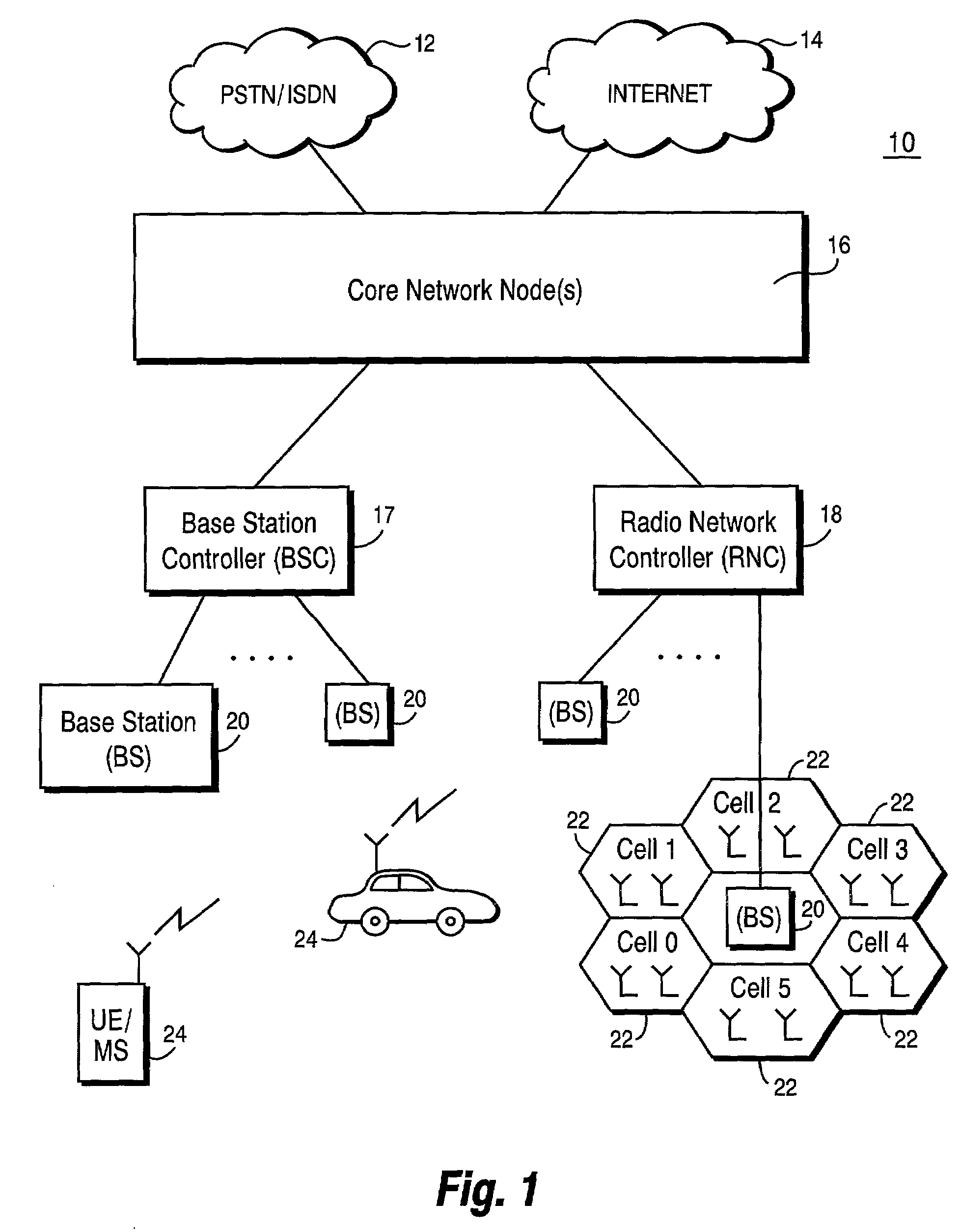
[0028]In the following description, for purposes of explanation and not limitation, specific details are set forth, such as particular embodiments, circuits, signal formats, techniques, etc. in order to provide a thorough understanding of the present invention. However, it will be apparent to one skilled in the art that the present invention may be practiced in other embodiments that depart from these specific details. For example, while the present invention is described in the context of a base station receiver, the present invention may be applied to any receiver, e.g., in a mobile station. In other instances, detailed descriptions of well-known methods, devices, and circuits are omitted so as not to obscure the description of the present invention with unnecessary detail. Moreover, individual function blocks are shown in some of the figures. Those skilled in the art will appreciate that the functions may be implemented using individual hardware circuitry, using software function...


PUM


Abstract

The present invention provides a search window delay tracking procedure for use in a multipath search processor of a CDMA radio receiver. A channel impulse response is estimated for a received signal containing plural paths, each path having a corresponding path delay. A search window defines a delay profile that contains the plural paths of the received signal. A mean or average delay is calculated for the estimated channel impulse response (CIR), and an error is determined between the mean CIR delay and a desired or target delay position of the Cir. search window. An adjustment is made to reduce that error to align the targeted position of the search window and the mean CIR delay. A Doppler frequency is estimated for each path. The adjustment is made taking into account a Doppler effect caused by relative movement between the transmitter and receiver.

Description

FIELD OF THE INVENTION[0001]The present invention relates to code division multiple access (CDMA) communication in cellular radio telephone communication systems, and more particularly, to a multipath search processor employed in a CDMA RAKE type receiver.BACKGROUND AND SUMMARY OF THE INVENTION[0002]Direct sequence code division multiple access (DS-CDMA) allows signals to overlap in both time and frequency so that CDMA signals from multiple users simultaneously operate in the same frequency band or spectrum. In principle, a source information digital data stream to be transmitted is impressed upon a much higher rate data stream generated by a pseudo-random noise (PN) code generator. This combining of a higher bit rate code signal with a lower bit rate data information stream “spreads” the bandwidth of the information data stream. Accordingly, each information data stream is allocated a unique PN or spreading code (or a PN code having a unique offset in time) to produce a signal that...

Claims


Application Information

Patent Timeline
Patent Type & Authority Patents(United States)
IPC IPC(8): H04Q7/20H04B1/60H04B17/00H04B17/02H04B1/707H04B1/7113H04B1/7117H04B17/40
CPCH04B1/7113H04B2001/70706H04B1/7117
Inventor KLEIN, OLIVERHELD, INGOLF
Owner TELEFON AB LM ERICSSON (PUBL)
Learn More