
Method for designing a small antenna matched to an input impedance, and small antennas designed according to the method

a technology of input impedance and antenna design, applied in the field of small printed antennas, can solve the problems of lowering the cost of antennas and antenna integration in the system, limiting the size and form factor, and putting a major limit on the effect of size and form factor, and achieves the effects of small area, easy and inexpensive manufacturing, and high performan

Inactive Publication Date: 2006-06-06
VISHAY ADVANCED TECH LTD +1
View PDF4 Cites 15 Cited by
  • Summary
  • Abstract
  • Description
  • Claims
  • Application Information

AI Technical Summary

Benefits of technology

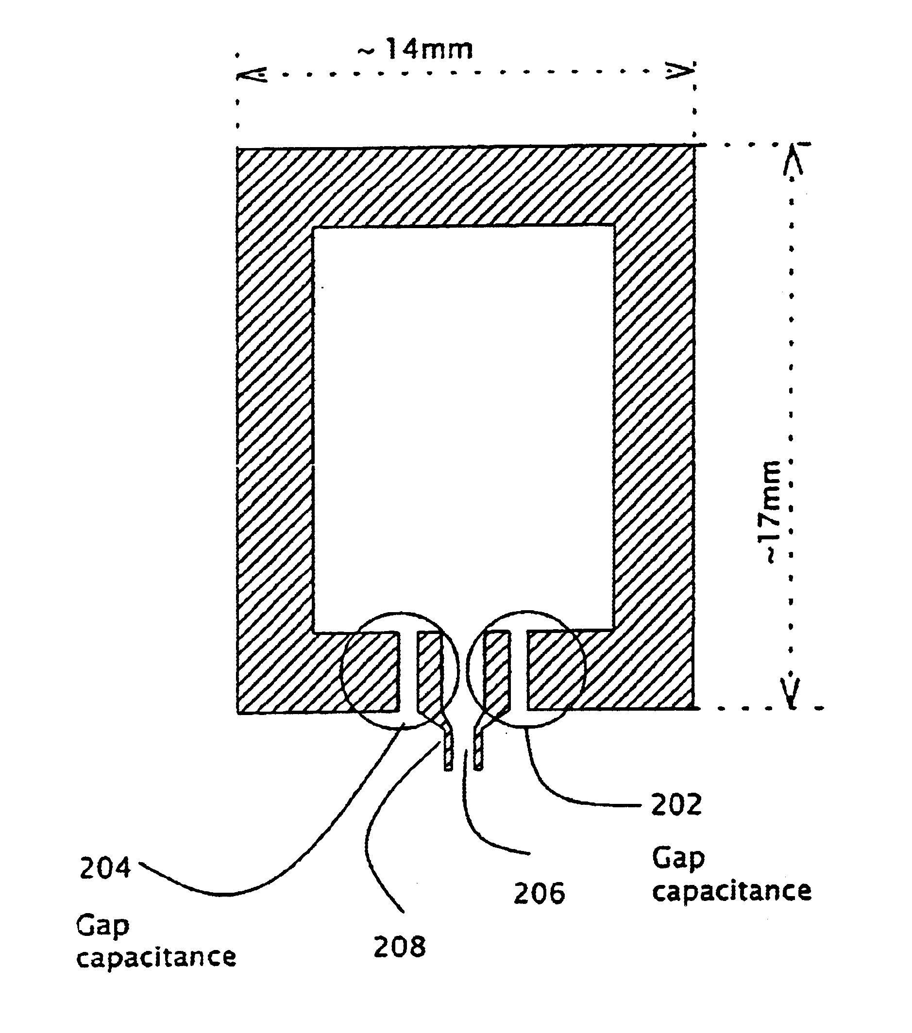
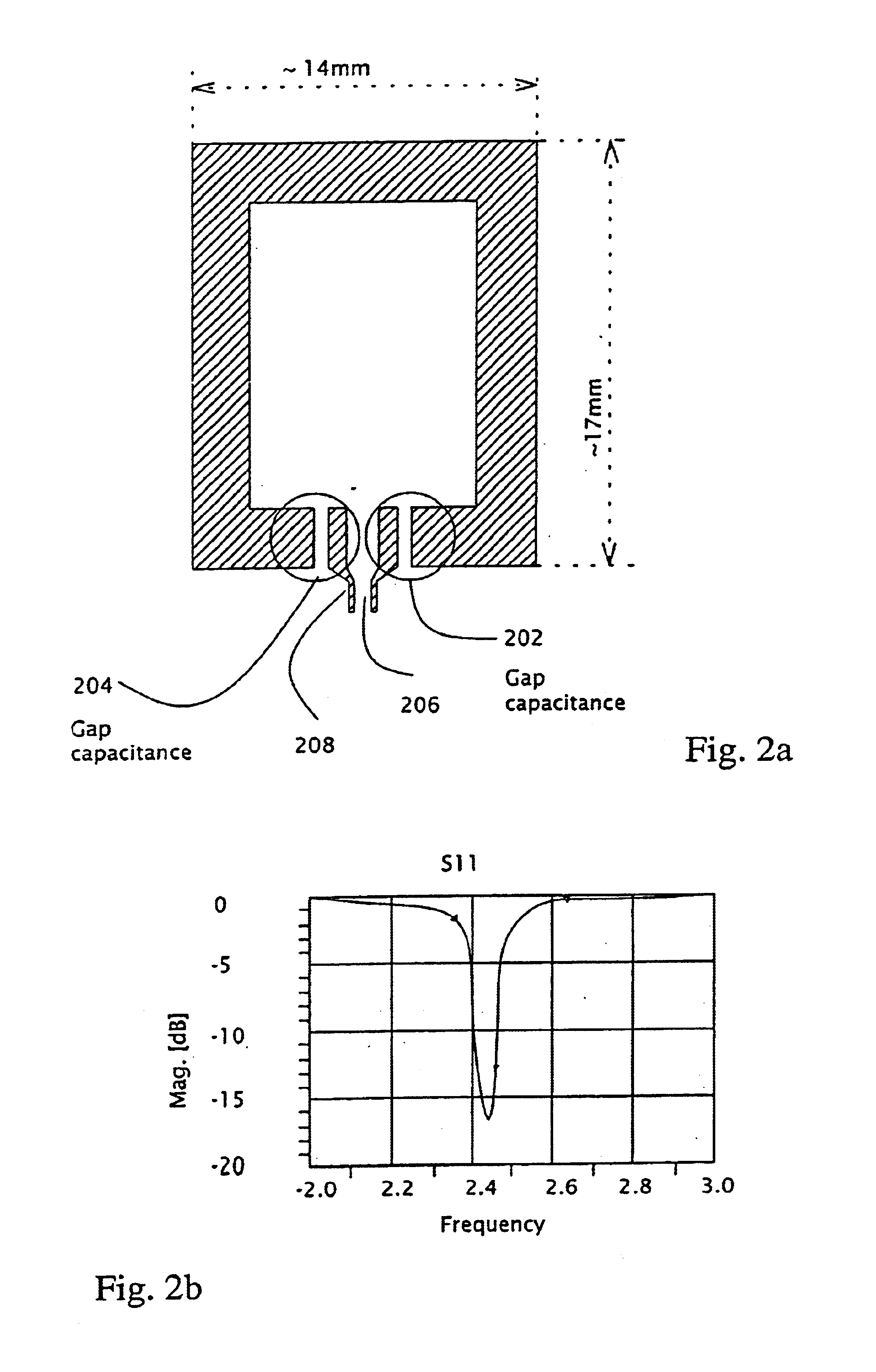
[0009]The present invention discloses an innovative, high performance, small area, matched antenna for transmitting and receiving RF signals in an extremely narrow bandwidth. More specifically, the antenna of the present invention is connected to an element that provides a very small capacitance, typically on the order of a few femtofarads to a few tens of femtofarads, the capacitance obtained preferably by a printed gap. The antenna is impedance-matched to a desired output impedance, does not require additional filtering, and can be manufactured easily and inexpensively. The antenna of the present invention can be used for (or in) RF transceivers for video, radio or any other type of data transmission; RF modules integrated in wireless applications such as input and control devices (like remote controllers for TV sets, wireless keyboards etc.); toys and games (wireless game pads, hand held games); home automation and security applications (like wireless light switches, wireless sensors for burglary alarm systems); wireless sensors for industrial automation; portable phones; wireless modems, etc.

Problems solved by technology

At present, the relevant industry faces some major difficulties, particularly regarding: 1) miniaturization of antennas without a significant impact on performance; 2) lowering the cost of antennas and of antenna integration in the system; 3) the need for a low-loss filter attached to the antenna as part of the front-end rejection of out-of-band signals; and 4) the need for a low loss impedance matching network that will also maintain a stable matching, with minimal effect of production tolerances and / or of near human presence.
For applications that wish to use such an antenna, this puts a major limit on size and form factor.
As a consequence, the effective dielectric constant increases, which decreases the effective wavelength of the electrical signal at the antenna, and therefore decreases its size.
However, dielectric loading significantly decreases antenna gain, as major parts of the transmitted or received energy dissipate in the dielectric material.
This usually deviates the radiation pattern, and is also considered relatively expensive.
Various other methods to decrease the size of the antenna usually result in complicated and expensive matching networks.
These methods usually use standard discrete matching components (capacitors, inductors), which have effects unwanted (such dominate especially in high frequencies, when the component dimensions become large with respect to the antenna dimensions or wavelength).
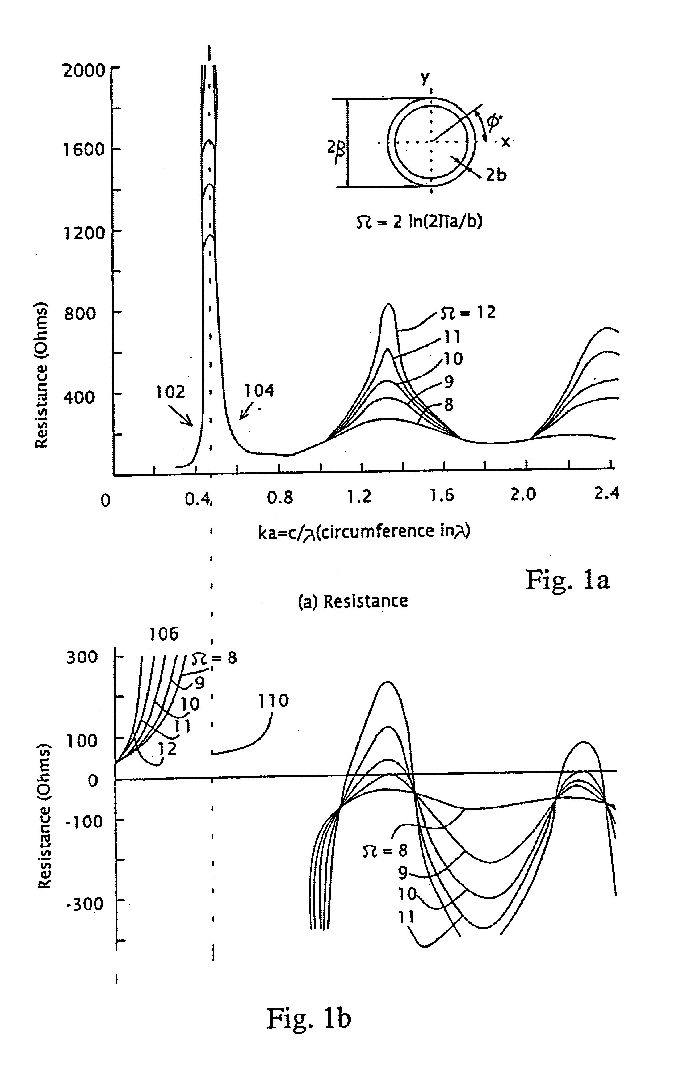
In many cases, a lot of energy is wasted on these components, so the antenna gain is decreased.
That means, for example, that they cannot be used to create a narrow-band antenna—as the central frequency of the impedance matching will vary from one device to another.
Therefore, expensive filters are installed at the antenna port.
Common filters usually suffer from ‘insertion loss’, which means that they also block some of the energy that is within the required frequency band.
Integration of the antenna with an RF amplifier also raises several problems.
Most antennas in the market today, are built to match the traditional 50 ohm impedance, which again, requires use of another lossy and expensive matching network in between.
As most antennas in the market today are created unbalanced, which means that they are fed with a non-differential transmission line such as a microstrip line, a “balun” component is required at the antenna chip interface, which also adds to the cost and to the energy losses.
Another difficulty that exists, is the fact that human presence near the antenna affects the performance of the antenna.
Since many applications today are ‘hand-held’ applications, there are major difficulties to maintain a matching to the antenna that is not affected by the human presence.

Method used


Image

  • Method for designing a small antenna matched to an input impedance, and small antennas designed according to the method
  • Method for designing a small antenna matched to an input impedance, and small antennas designed according to the method
  • Method for designing a small antenna matched to an input impedance, and small antennas designed according to the method

Examples


Embodiment Construction

[0021]The present invention is of a high performance, narrow bandwidth, impedance matched small antenna for short-range wireless applications. Specifically the antenna of the present applications is matched to the desired input impedance by choosing a special singular point. The matching is obtained by using a very small capacitance that is provided by an element which is serially connected to the antenna feeding port aid is an integral part of the antenna, such an element being preferably a printed gap.

[0022]As mentioned above, it is possible to overcome the present difficulties faced by antenna industry or RF module designers, by a unique and elegant technique, which is the essence of this invention. Generally, the design procedure starts by choosing to match the antenna in a singular region of its input impedance. A singular region is an interval in which the input impedance, both its real and its imaginary parts, have high derivatives with respect to the geometrical dimensions o...


PUM


Abstract

A method for designing a high performance, small antenna that is matched to a required output impedance, does not require filtering, is simple and inexpensive to manufacture, and is easily integrable with an RF power amplifier- with minimum cost, minimum external components and minimum energy losses. The method includes finding a singular point (102) in the impedance vs. antenna geometrical dimension / wavelength ratio graph, the singular point (102) exhibiting a high very high positive reactance, setting the antenna geometry to match this point, and canceling the very high positive reactance (high inductance) resulting from this match by adding to the antenna a very small capacitance, preferably provided by at least one gap capacitor (202) The antenna is preferably a loop antenna (200), and both the antenna and the gap capacitor (202) (204) are preferably implemented by printing methods on printed circuit board or ceramic substrates. The antenna (200) may also be implemented in non-differential designs.

Description

[0001]This application claims benefit of Ser. No. 60 / 292,938 filed May 24, 2001.FIELD AND BACKGROUND OF THE INVENTION[0002]The present invention relates to antennas, specifically small printed antennas for low cost, short range wireless applications, for example in wireless toys, Wireless keyboards, wireless security systems, RF based remote controllers for TV sets, etc. At present, the relevant industry faces some major difficulties, particularly regarding: 1) miniaturization of antennas without a significant impact on performance; 2) lowering the cost of antennas and of antenna integration in the system; 3) the need for a low-loss filter attached to the antenna as part of the front-end rejection of out-of-band signals; and 4) the need for a low loss impedance matching network that will also maintain a stable matching, with minimal effect of production tolerances and / or of near human presence.[0003]A traditional loop antenna is usually made to resonate when its physical length equa...

Claims


Application Information

Patent Timeline
IPC IPC(8): H01Q7/00H01Q1/36H01Q1/38
CPCH01Q1/36H01Q7/005H01Q7/00H01Q1/38
Inventor SHAMIR, ADIGAZIT, MEIR
Owner VISHAY ADVANCED TECH LTD
Learn More