
Information recording and reproducing apparatus and method, and signal decoding circuit for performing timing recovery

a signal decoding circuit and information recording and reproducing technology, applied in the field of information method, can solve the problems of deteriorating format efficiency of magnetic recording and reproducing apparatus, difficulty in obtaining no consideration of frequency offset, etc., to achieve a wide frequency lead-in range, high density recording, and shorten the length of the preamble

Inactive Publication Date: 2006-05-30
TOSHIBA STORAGE DEVICE CORP
View PDF5 Cites 81 Cited by
  • Summary
  • Abstract
  • Description
  • Claims
  • Application Information

AI Technical Summary

Benefits of technology

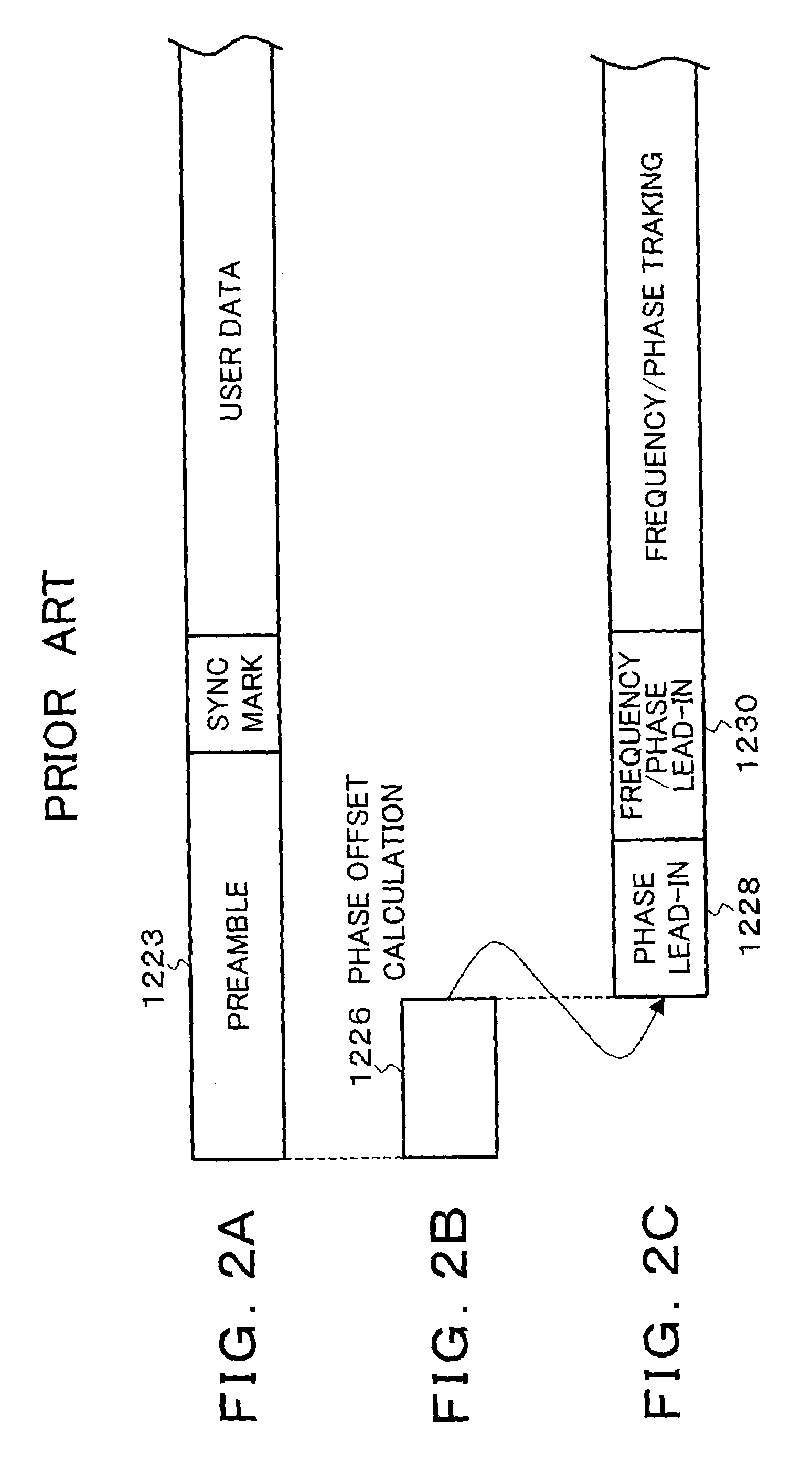
[0011]The timing recovery unit comprises: a buffer which stores data obtained by sampling a head reproduction signal by a fixed clock; a phase offset detector which detects a phase offset from a data head area in parallel with data writing into the buffer; a frequency offset detector which detects a frequency offset from the data head area in parallel with the data writing into the buffer; and a PLL which initially sets correcting states of the detected phase offset and frequency offset and, thereafter, performs a phase lead-in and a frequency lead-in in the head area while the data is read out from the buffer. According to the invention, therefore, as for the compensation by the error detection in the head portion of a preamble area, by detecting and compensating errors with respect to not only the phase but also the frequency, the phase lead-in and the frequency lead-in are performed in a short time, the preamble area can be shortened, and a frequency lead-in range can be widened.
[0047]the timing recovery unit is corrected by the detected frequency error, thereby allowing a loop operation to be started.

Problems solved by technology

However, no consideration is given to a frequency offset, and it is difficult to obtain a wide frequency lead-in range.
There is a problem such that format efficiency of the magnetic recording and reproducing apparatus deteriorates.

Method used


Image

  • Information recording and reproducing apparatus and method, and signal decoding circuit for performing timing recovery
  • Information recording and reproducing apparatus and method, and signal decoding circuit for performing timing recovery
  • Information recording and reproducing apparatus and method, and signal decoding circuit for performing timing recovery

Examples


embodiment

Fundamental Embodiment

[0096]FIG. 4 is a block diagram of a hard disk drive to which the invention is applied. The hard disk drive is constructed by an SCSI controller 10, a drive control 12, and a disk enclosure 14. Naturally, an interface with a host is not limited to the SCSI controller 10 but other proper interface controller can be used. The SCSI controller 10 is provided with: an MCU (Main Control Unit) 16; a memory 18 using a DRAM or an SRAM which is used as a control storage; a program memory 20 using a non-volatile memory such as a flash memory or the like for storing a control program; a hard disk controller (HDC) 22; and a data buffer 24. A drive interface logic 26, a DSP 28, a read channel (RDC) 30, and a servo driver 32 are provided for the drive control 12. A head IC 34 is further provided for the disk enclosure 14. Combination heads 36-1 to 36-6 each having a recording head and a reproducing head are connected to the head IC 34, respectively. The combination heads 36-1...


PUM


Abstract

A timing recovery unit detects a phase offset and a frequency offset from a head area of reproduction data and initially corrects them. The timing recovery unit stores data in which a head reproduction signal has been made to be discrete by a fixed clock into a buffer. A phase offset detector detects the phase offset from the data head area in parallel with the operation for writing the data into the buffer. At the same time, a frequency offset detector detects the frequency offset from the data head area in parallel with the operation for writing the data into the buffer. A correction value of the detected phase offset and a correction value of the detected frequency offset are initially set into a digital PLL. While the data is read out from the buffer, a frequency lead-in and a phase lead-in are executed in the head area.

Description

BACKGROUND OF THE INVENTION[0001]1. Field of the Invention[0002]The invention relates to an information recording and reproducing apparatus of a magnetic disk, an MO, an optical disk, a magnetic tape, or the like, an information recording and reproducing method, and a signal decoding circuit. More particularly, the invention relates to information recording and reproducing apparatus and method and a signal decoding circuit, for performing a timing recovery after a head reproduction signal is made discrete by an asynchronous clock.[0003]2. Description of the Related Arts[0004]In a conventional timing reproduction loop for a timing recovery of a read channel LSI, a sampling clock in an A / D converter and a symbol rate clock for making discrimination are the same. To obtain optimum discrimination timing, therefore, it is necessary for directly controlling a phase of the sampling clock of the A / D converter. Aside from it, there is also a method whereby the sampling clock of the A / D conve...

Claims


Application Information

Patent Timeline
IPC IPC(8): G11B5/35G11B5/09G11B20/14G11B7/005G11B20/10G11B20/18H04B3/06
CPCG11B5/09G11B20/18G11B20/10009
Inventor YAMAZAKI, AKIHIROSUGAWARA, TAKAOTAKATSU, MOTOMUSAWADA, MASARU
Owner TOSHIBA STORAGE DEVICE CORP
Learn More