
Apparatus and method for measurement of communication quality in CDMA system

a communication quality and mobile communication technology, applied in the direction of synchronisation signal speed/phase control, transmission monitoring, synchronisation arrangement, etc., can solve the problem that the obtained measured value cannot be accurate, the 3-step cell search method cannot be effective synchronization detection method, and the phase variation of the desired signal vector due to fading becomes not ignorable, etc. problem, to achieve the effect of high precision, high precision and high precision

Active Publication Date: 2006-05-23
NTT DOCOMO INC
View PDF8 Cites 3 Cited by
  • Summary
  • Abstract
  • Description
  • Claims
  • Application Information

AI Technical Summary

Benefits of technology

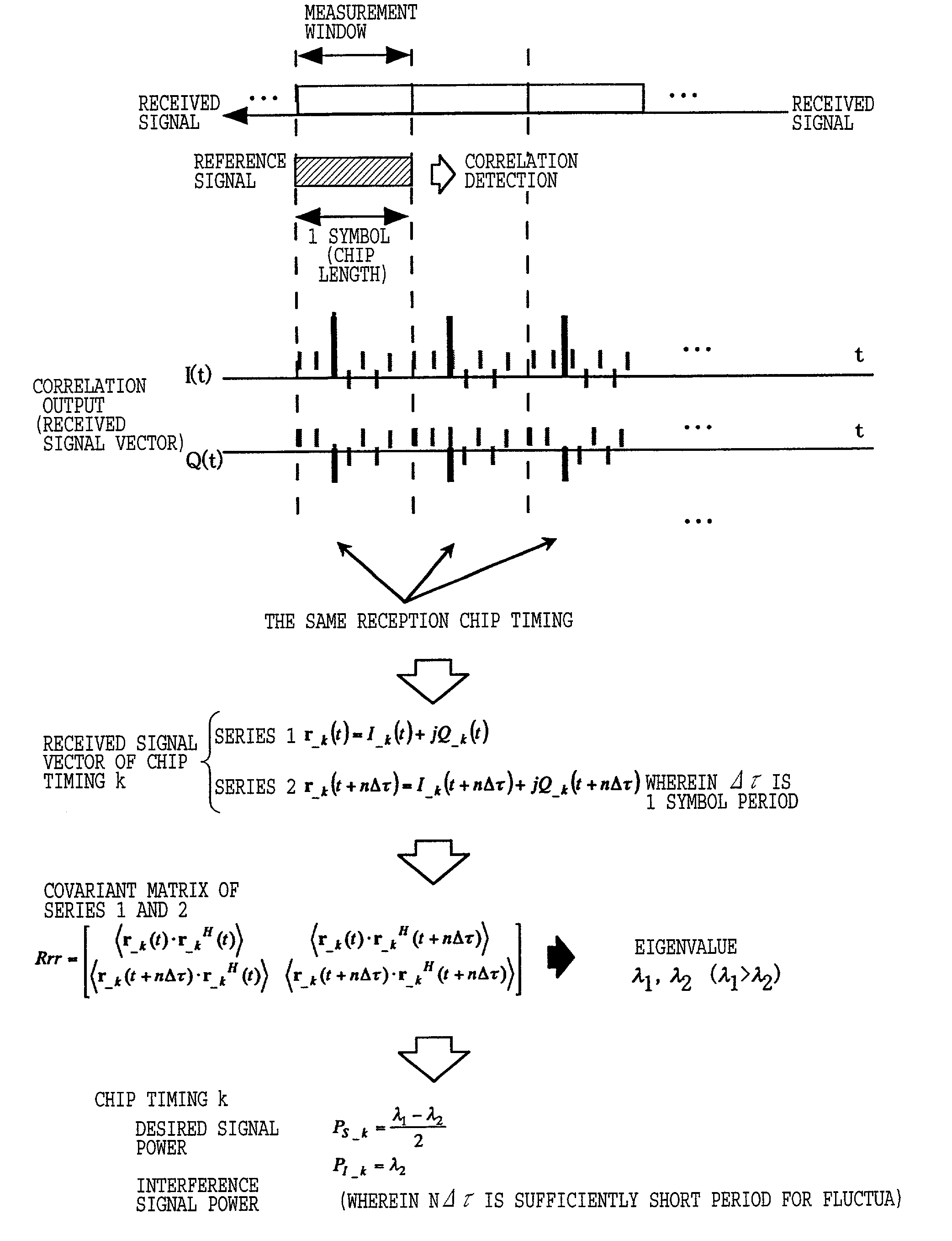
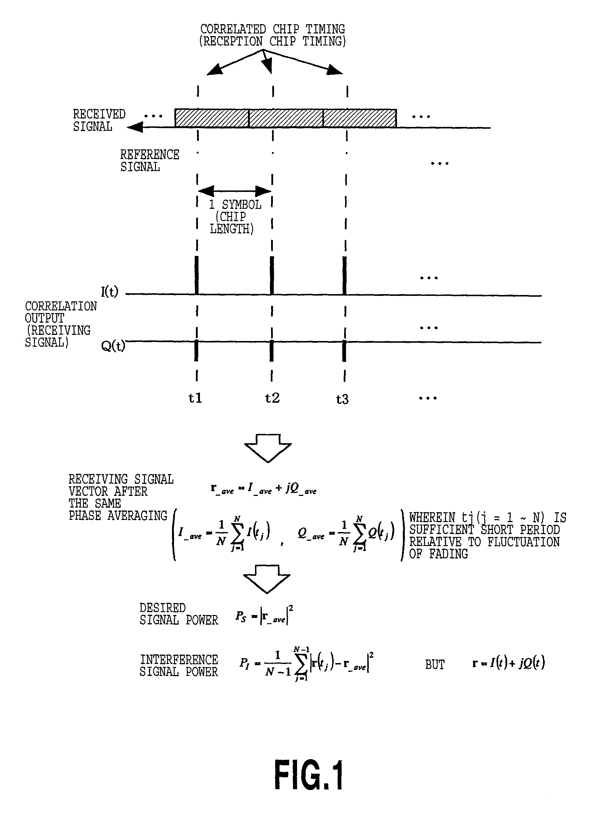
[0017]It is therefore an object of the present invention is to provide a communication quality measuring method and an apparatus for measurement of communication quality (propagation characteristics) with high precision and high efficiency by taking all chip timing in a range set at a reception chip timing detected in a preliminary step of measurement, and generating two time series having several period of time difference from a received signal vector of the same chip timing obtained within a certain given period.
[0018]Another object of the present invention is to provide a synchronization detecting method and apparatus which can perform detection of synchronization for measurement at high speed, high precision and high reliability.
[0019]A further object of the present invention to provide a synchronization detecting method and apparatus which can perform detection of synchronization for measurement at high speed, high precision and high reliability while transmit diversity is applied.

Problems solved by technology

When number of samples is set to be the same number as that when the transmit diversity is not applied, phase variation of the desired signal vector due to fading becomes not ignorable.
Therefore, obtained measured value cannot be correct.
However, in measurement system or the like, in which the base station as object for measurement (objective scrambling code), the 3-step cell search method cannot be effective synchronization detection method.
In such case, it is not efficient to transmit three channels corresponding PSCH, SSCH and CPICH by the pseudo base station for measurement.
Also, it is not efficient for constraint condition for number of samples and sampling interval upon deriving the desired signal power, the interference signal power in each reception chip timing.
On the other hand, it is not efficient in that number of samples and sampling interval are different depending upon whether transmit diversity is applied or not.
Furthermore, in the conventional method, upon performing detection of synchronization of the channel to be measured, channel other than the channel to be measured is required to be inefficient.

Method used


Image

  • Apparatus and method for measurement of communication quality in CDMA system
  • Apparatus and method for measurement of communication quality in CDMA system
  • Apparatus and method for measurement of communication quality in CDMA system

Examples


first embodiment

[0119]In the synchronization detection method, when the received signal power of the chip timing matching with an effective path position for communication is higher than or equal to a received signal power at other timing, detection of the synchronization chip timing is successful. Accordingly, by setting the chip length (unit for blocking) for partial correlation longer, probability of success in detection of the synchronization chip timing becomes higher.

[0120]FIG. 5 is explanatory illustration of operation in the case where a matched filter is used in the correlation detecting portion of the mobile station, to which the present invention is applied. The matched filter is used for calculation of partial correlation to rewrite code in the matched filter per 1 / 15 msec. As shown in FIG. 5, rewriting code to be written in the matched filter is consisted of 256 chips extracted among 150 timing candidates #1 to #150.

[0121]By the first embodiment, a period required for detecting the syn...

second embodiment

[0124]FIG. 7 shows the case where the power averaging process is performed as equalizing process in the synchronization detecting method. A received signal vector at a timing t of the synchronization timing candidate #i and its chip number k in the symbol, is assumed as (Ii—k(t), Qi—k(t)), the synchronization timing candidate after equalization is #i, and a power at chip number k in its symbol is assumed as Pi—k.

[0125]In the power averaging process, the instantaneous received signal power is calculated from the received signal vector of each synchronization timing candidate, and subsequently, N in number of the calculated received signal power is averaged per synchronization timing candidate. By the power value after equalization thus obtained, the synchronization chip timing of the channel to be measured is determined. The power averaging process is characterized in that when sample number N is increased, a standard deviation of the received signal power at a timing other than the ...

third embodiment

[0133]In the third embodiment, averaging operation is repeated twice. At the first stage of averaging, N1 in number of vector averaging process is performed per synchronization timing candidate. Subsequently, the power value is derived from the received signal vector after vector averaging for deriving N2 in number of averaged values. At the second stage, the chip timing where the received signal power after averaging becomes maximum, is detected to the synchronization chip timing of the channel to be measured.

[0134]In the third embodiment, at first, in the first stage averaging, the average value of the received signal power in the synchronization chip timing other than the true synchronization chip timing becomes small for N1 in number of samples. Subsequently, by averaging in the second stage, the standard deviation becomes smaller than N2 in number of samples. As a result, probability of success in detection of synchronization becomes further higher in comparison with the case o...


PUM


Abstract

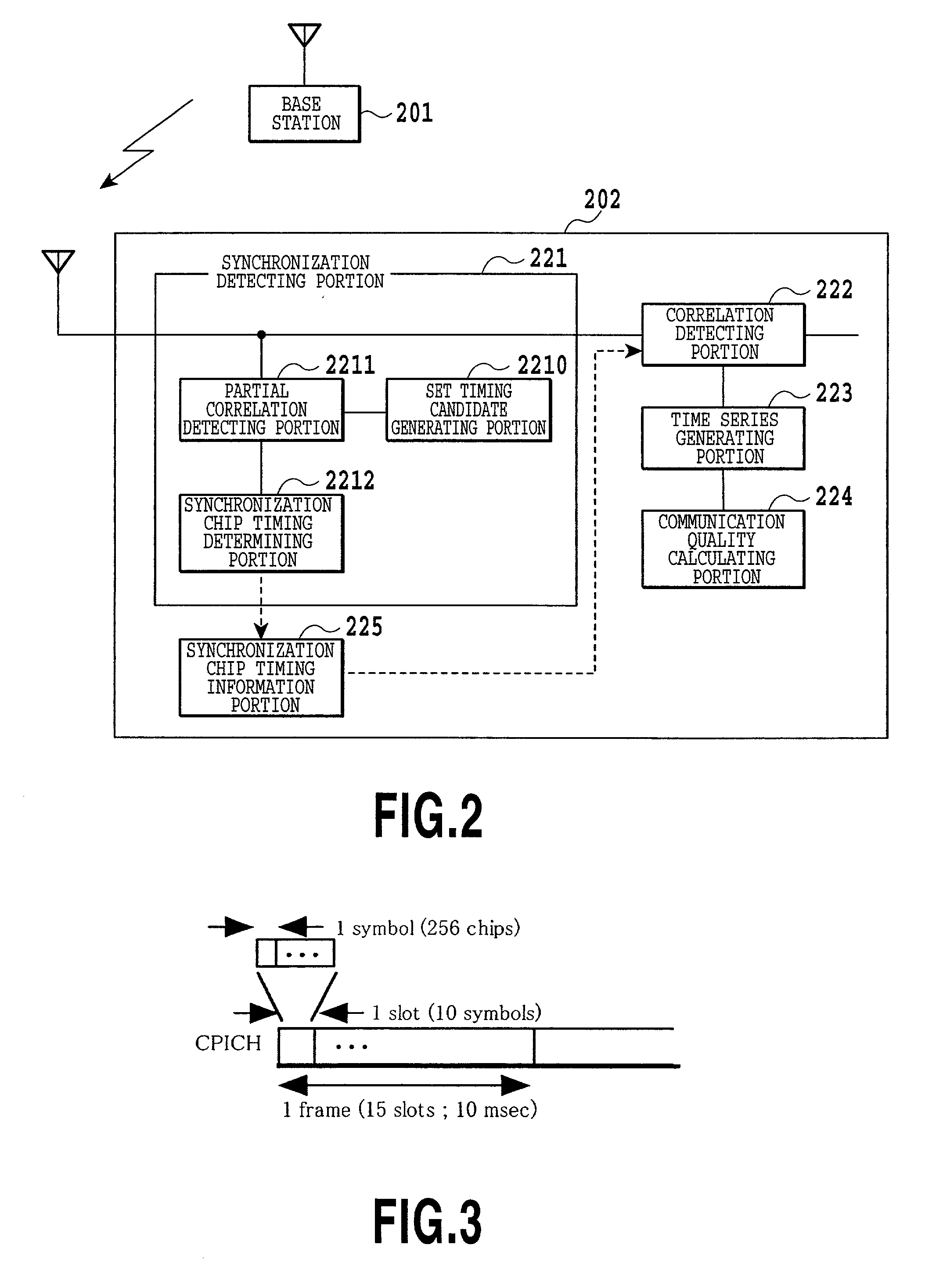
In order to perform synchronization detection with high speed, high precision and high reliability and to measure communication quality (propagation characteristics) at high precision and high efficiency, a mobile station includes synchronization detecting portion for detecting synchronization chip timing of channel to be measured, a synchronization chip timing information portion accumulating information of detected synchronization chip timing, a correlation detecting portion deriving a correlation value between spreading code of the channel to be measured and a received signal for performing communication with a base station and measurement of communication quality with taking the detected synchronization chip timing as a reception chip timing, a time series generating portion for generating a time series data of received signal vector after correlation detection, and a communication quality calculating portion for calculating communication quality from generated time series data.

Description

[0001]This application claims priority under 35 U.S.C. 119 to Patent Application Nos. 2000-105485 filed Apr. 6, 2000, 2000-105486 filed Apr. 6, 2000, and 2001-53033 filed Feb. 27, 2001 in Japan, the contents of which are incorporated hereinto by reference.BACKGROUND OF THE INVENTION[0002]1. Field of the Invention[0003]The present invention relates generally to a method and an apparatus for measurement of communication quality in a mobile communication system using a CDMA cellular system. More particularly, the invention relates to a method and an apparatus for measuring desired signal power, interference signal power, SIR and propagation paths between transmitter and receiver, as communication quality. Also the invention relates to a method and a system for detection of synchronization suitable for measuring communication quality using channels spread by relatively long known spreading code constantly transmitted by installed base stations.[0004]2. Description of the Related Art[000...

Claims


Application Information

Patent Timeline
Patent Type & Authority Patents(United States)
IPC IPC(8): H04B1/69H04B1/38H04B1/10H04B1/707H04B1/7075H04B7/26H04B17/00H04B17/318H04B17/336H04B17/345H04L7/00H04L7/04H04W24/00H04W56/00H04W88/02
CPCH04B1/1027H04B1/707H04B17/336H04L1/20H04B1/7115H04B1/7093H04B1/7073H04B17/00
Inventor IMAI, TETSUROMORI, SHINICHI
Owner NTT DOCOMO INC
Learn More