
Lithographic apparatus, device manufacturing method, and device manufactured thereby

a technology of lithographic apparatus and manufacturing method, which is applied in the direction of duplicating/marking methods, decorative arts, photographic processes, etc., can solve the problems of high cost of stage to stage overlay performance, and achieve the effect of improving image performance in lithographic processes

Inactive Publication Date: 2006-05-16
ASML NETHERLANDS BV
View PDF10 Cites 16 Cited by
  • Summary
  • Abstract
  • Description
  • Claims
  • Application Information

AI Technical Summary

Benefits of technology

[0013]It is an aspect of the present invention to allow improved image performance in lithographic processes using multi-stage lithography apparatus.
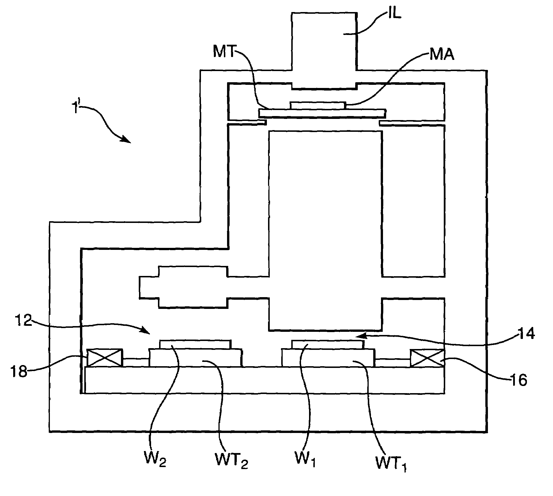
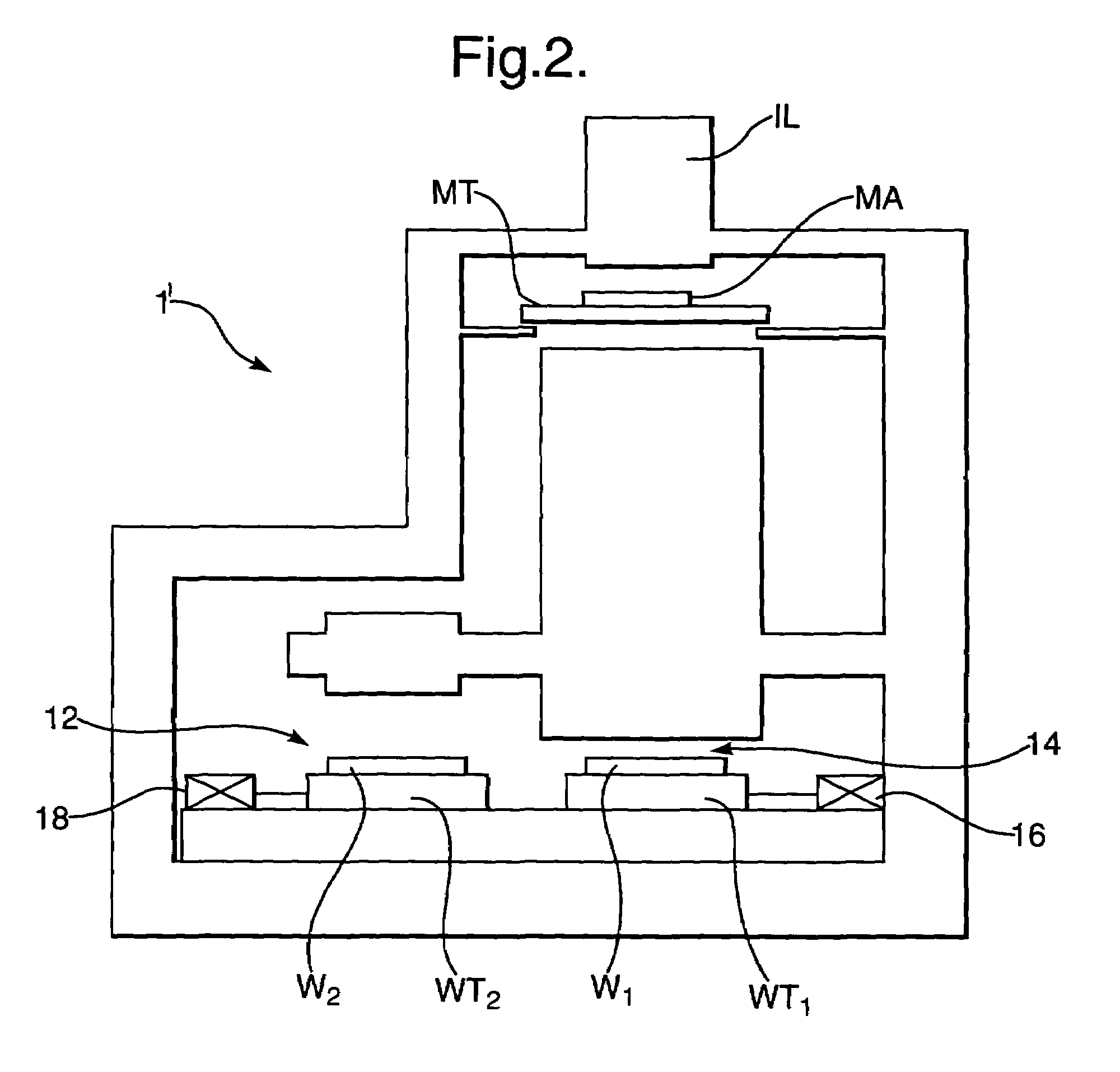
[0014]This and other aspects are achieved according to the invention in a lithographic apparatus including apparatus a radiation system constructed and arranged to provide a beam of radiation; a support constructed and arranged to support a patterning device, the patterning device constructed and arranged to pattern the beam of radiation according to a desired pattern; a first substrate holder constructed and arranged to hold a substrate; a second substrate holder constructed and arranged to hold a substrate; a projection system constructed and arranged to project the patterned beam of radiation onto a target portion of the substrate; and a controller that controls the apparatus such that when imaging a second pattern onto a substrate having a first pattern imaged thereon effects of differences between the two substrate holders are reduced.
[0015]By accounting for differences between the substrate holders, the apparatus according to the present invention can achieve improved imaging performance. The inventors have been able to achieve overlay performance improvement of several nanometers. Manufacture of stages giving this level of stage to stage overlay performance would be extremely costly, if it were possible at all. Thus, the present invention allows increased performance without additional engineering and manufacturing expenses.
[0018]According to a further aspect of the invention there is provided a device manufacturing method including projecting a patterned beam of radiation onto a target portion of a layer of radiation-sensitive material at least partially covering a substrate; providing a first and second substrate holder to hold the substrate during imaging; controlling the imaging of a second pattern onto a substrate containing a first pattern to reduce effects of difference between the two substrate holders.

Problems solved by technology

Manufacture of stages giving this level of stage to stage overlay performance would be extremely costly, if it were possible at all.

Method used


Image

  • Lithographic apparatus, device manufacturing method, and device manufactured thereby
  • Lithographic apparatus, device manufacturing method, and device manufactured thereby
  • Lithographic apparatus, device manufacturing method, and device manufactured thereby

Examples


Embodiment Construction

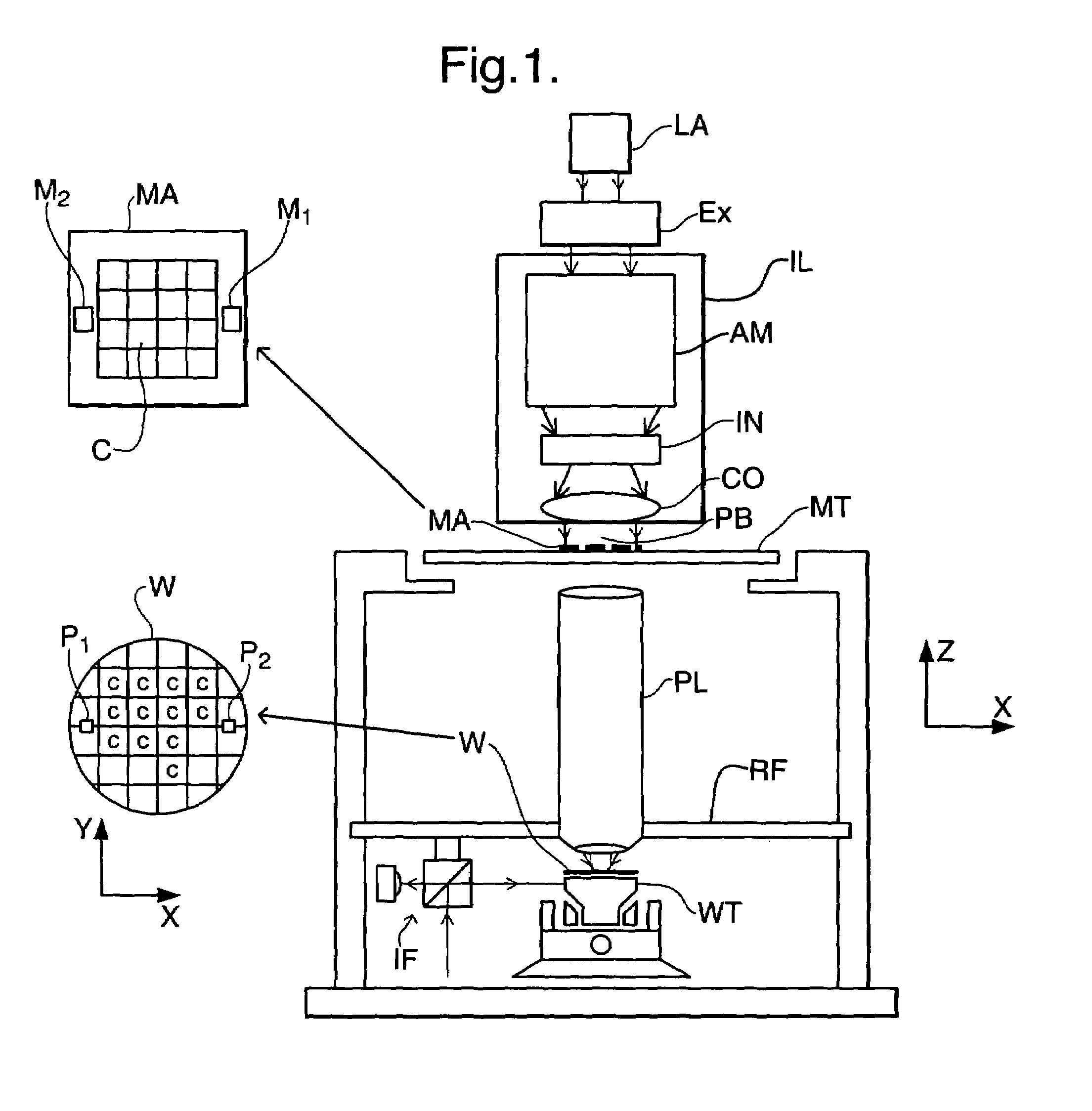
[0028]FIG. 1 schematically depicts a lithographic projection apparatus 1 according to an embodiment of the invention. The apparatus includes a radiation system Ex, IL constructed and arranged to supply a beam PB of radiation (e.g. UV or EUV radiation, such as, for example, generated by an excimer laser operating at a wavelength of 248 nm, 193 nm or 157 nm, or by a laser-fired plasma source operating at 13.6 nm). In This embodiment, the radiation system also comprises a radiation source LA. The apparatus also includes a first object (mask) table MT provided with a mask bolder constructed and arranged to hold a mask MA (e.g. a reticle), and connected to a first positioning device PM to accurately position the mask with respect to a projection system or lens PL; a second object (substrate) table WT provided with a substrate holder constructed and arranged to hold a substrate W (e.g. a resist-coated silicon wafer), and connected to a second positioning device PW to accurately position t...


PUM

PropertyMeasurementUnit
Areaaaaaaaaaaa
Sensitivityaaaaaaaaaa

Abstract

A lithographic projection apparatus having at least two substrate holders is controlled to reduce effects of differences in images caused by differences between the two substrate holders. The apparatus includes an internal or external detector that identifies a substrate and associates it with a respective one of the substrate holders. A controller ensures that either the substrate is processed on the appropriate holder or that correction is applied to the imaging. In an alternate embodiment, the substrate is associated with a respective one of the substrate holders and is consistently processed using that substrate holder without further identification steps.

Description

[0001]This application claims priority to European Application 02252526.5, filed Apr. 9, 2002, the entire contents of which are incorporated by reference.BACKGROUND OF THE INVENTION[0002]1. Field of the Invention[0003]The present invention relates to a lithographic projection apparatus, a device manufacturing method and a device manufactured thereby.[0004]2. Description of the Related Art[0005]The term “patterning device” as here employed should be broadly interpreted as referring to device that can be used to endow an incoming radiation beam with a patterned cross-section, corresponding to a pattern that is to be created in a target portion of the substrate. The term “light valve” can also be used in this context. Generally, the pattern will correspond to a particular functional layer in a device being created in the target portion, such as an integrated circuit or other device (see below). An example of such a patterning device is a mask. The concept of a mask is well known in lit...

Claims


Application Information

Patent Timeline
IPC IPC(8): G03B27/32G03B27/42G03F7/20H01L21/027
CPCG03F7/70633G03F7/70733Y10T428/24802Y10T428/24835G03F7/20
Inventor ROSSING, HARM ROELOFVAN DEN BRINK, MARINUS AARTGEORGE, RICHARD ALEXANDER
Owner ASML NETHERLANDS BV
Learn More