
Projection optical system, exposure apparatus, and exposure method

a projection optical system and optical system technology, applied in the field of catadioptric projection optical system, exposure apparatus, exposure method, can solve the problems of increasing the scale of the projection optical system, inability to avoid an increase in the scale of the reflecting optical member, and more difficult to implement optical, etc., to achieve good suppression of reflection loss on optical surfaces, excellent imaging performance, and large effective image-side numerical apertur

Active Publication Date: 2007-02-15
NIKON CORP
View PDF14 Cites 54 Cited by
  • Summary
  • Abstract
  • Description
  • Claims
  • Application Information

AI Technical Summary

Benefits of technology

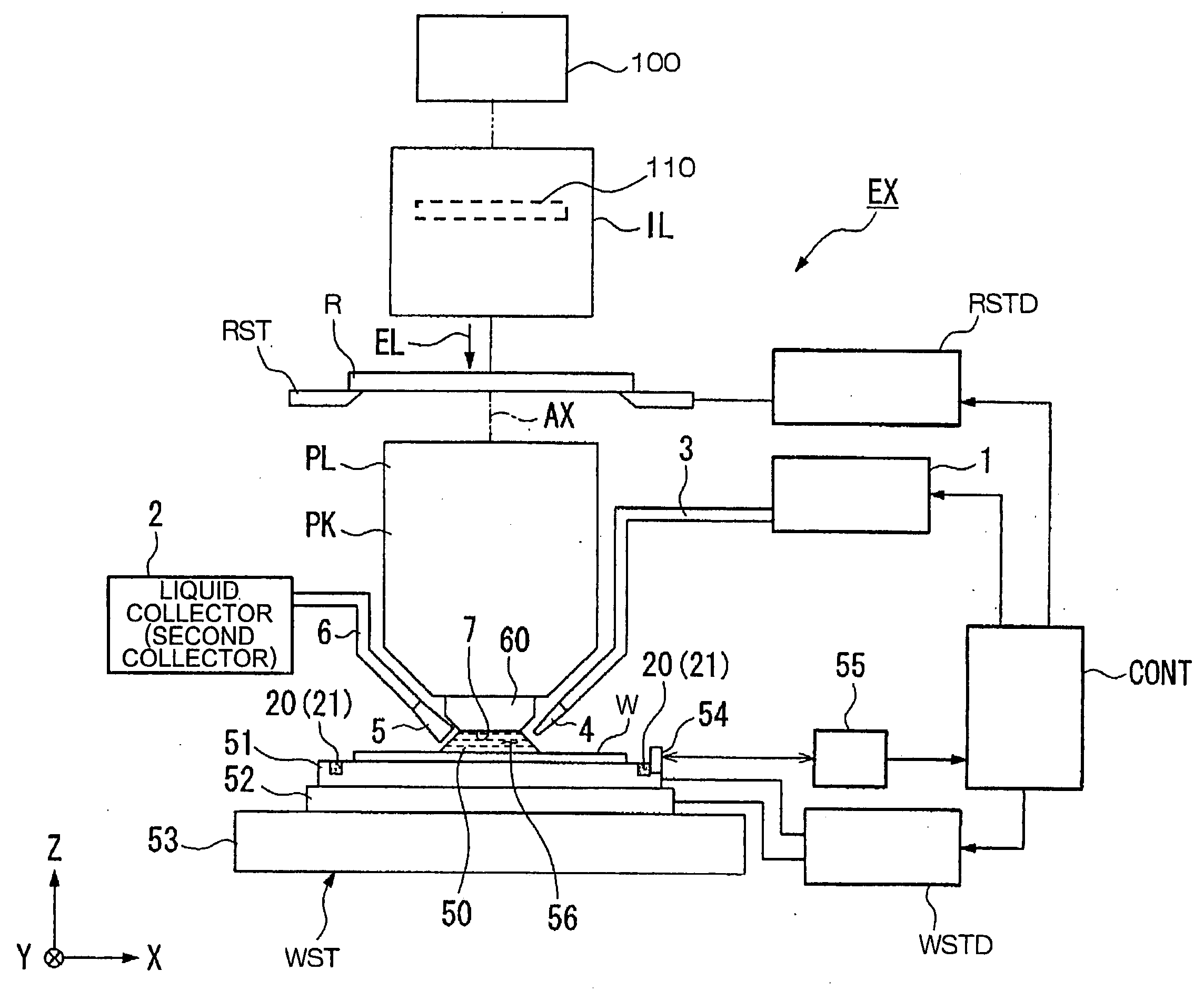
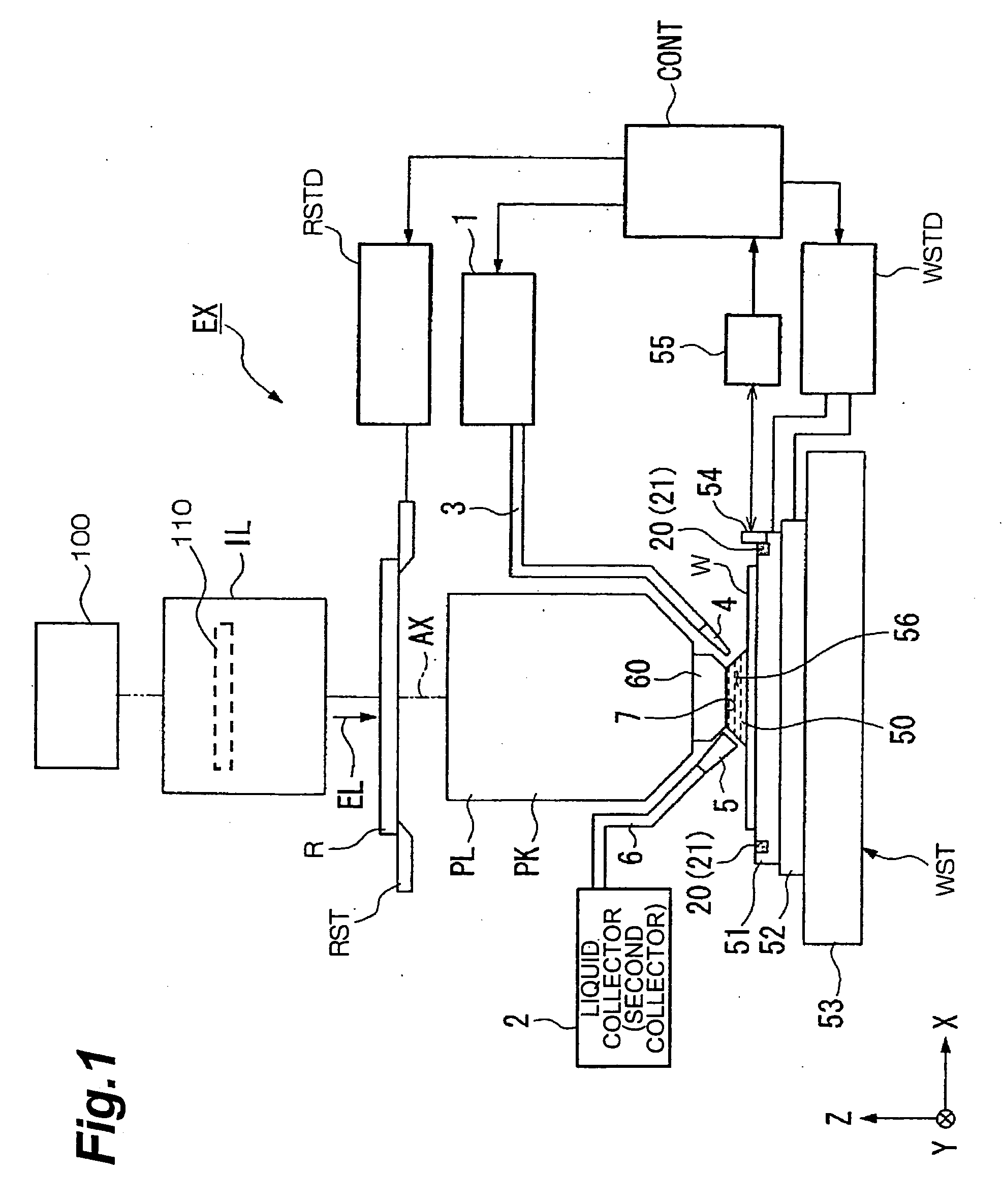
[0009] A first object of the embodiment is to provide a relatively compact projection optical system having excellent imaging performance as well corrected for various aberrations, such as chromatic aberration and curvature of field, and being capable of securing a large effective image-side numerical aperture while well suppressing the reflection loss on optical surfaces.
[0012] A second object of the embodiment is to achieve a large numerical aperture, without increase in the scale of optical members forming a catadioptric projection optical system.
[0013] A third object of the embodiment is to provide an exposure apparatus and exposure method capable of performing an exposure to transcribe a fine pattern with high accuracy through a projection optical system having excellent imaging performance and having a large effective image-side numerical aperture and therefore a high resolution. In order to achieve the above-described first object, a projection optical system according to a first aspect of the embodiment is a catadioptric projection optical system for forming a reduced image of a first surface on a second surface,

Problems solved by technology

In the case where the projection optical system is composed of only reflecting optical members and in the case where the projection optical system is composed of a combination of refracting optical members with reflecting optical members, with increase in the numerical aperture, it becomes more difficult to implement optical path separation between a beam entering a reflecting optical member and a beam reflected by the reflecting optical member and it is infeasible to avoid an increase in the scale of the reflecting optical member, i.e., an increase in the scale of the projection optical system.

Method used


Image

  • Projection optical system, exposure apparatus, and exposure method
  • Projection optical system, exposure apparatus, and exposure method
  • Projection optical system, exposure apparatus, and exposure method

Examples


first example

[0173]FIG. 5 is an illustration showing a lens configuration of the projection optical system according to the first example of the present embodiment. With reference to FIG. 5, in the projection optical system PL according to the first example, the first imaging optical system G1 is composed of the following components arranged in order from the reticle side along the traveling direction of light: a biconvex lens L11 whose convex surface of aspherical shape is kept toward the wafer; a biconvex lens L12; a negative meniscus lens L13 whose concave surface of aspherical shape is kept toward the reticle; and a first concave reflecting mirror CM1. In the first imaging optical system G1, a reflecting surface of second concave reflecting mirror CM2 for reflecting the light reflected by the first concave reflecting mirror CM1 and transmitted by the negative meniscus lens L13, toward the second imaging optical system G2 is placed in a region not including the optical axis AX between the bic...

second example

[0181]FIG. 7 is an illustration showing a lens configuration of the projection optical system according to the second example of the present embodiment. With reference to FIG. 7, in the projection optical system PL according to the second example, the first imaging optical system G1 is composed of the following components in order from the reticle side along the traveling direction of light: a biconvex lens L11 whose convex surface of aspherical shape is kept toward the wafer; a biconvex lens L12; a negative meniscus lens L13 whose concave surface of aspherical shape is kept toward the reticle; and a first concave reflecting mirror CM1. In the first imaging optical system G1, a reflecting surface of a second concave reflecting mirror CM2 for reflecting the light reflected by the first concave reflecting mirror CM1 and transmitted by the negative meniscus lens L13, toward the second imaging optical system G2 is placed in the region not including the optical axis AX between the biconv...

third example

(Specifications)

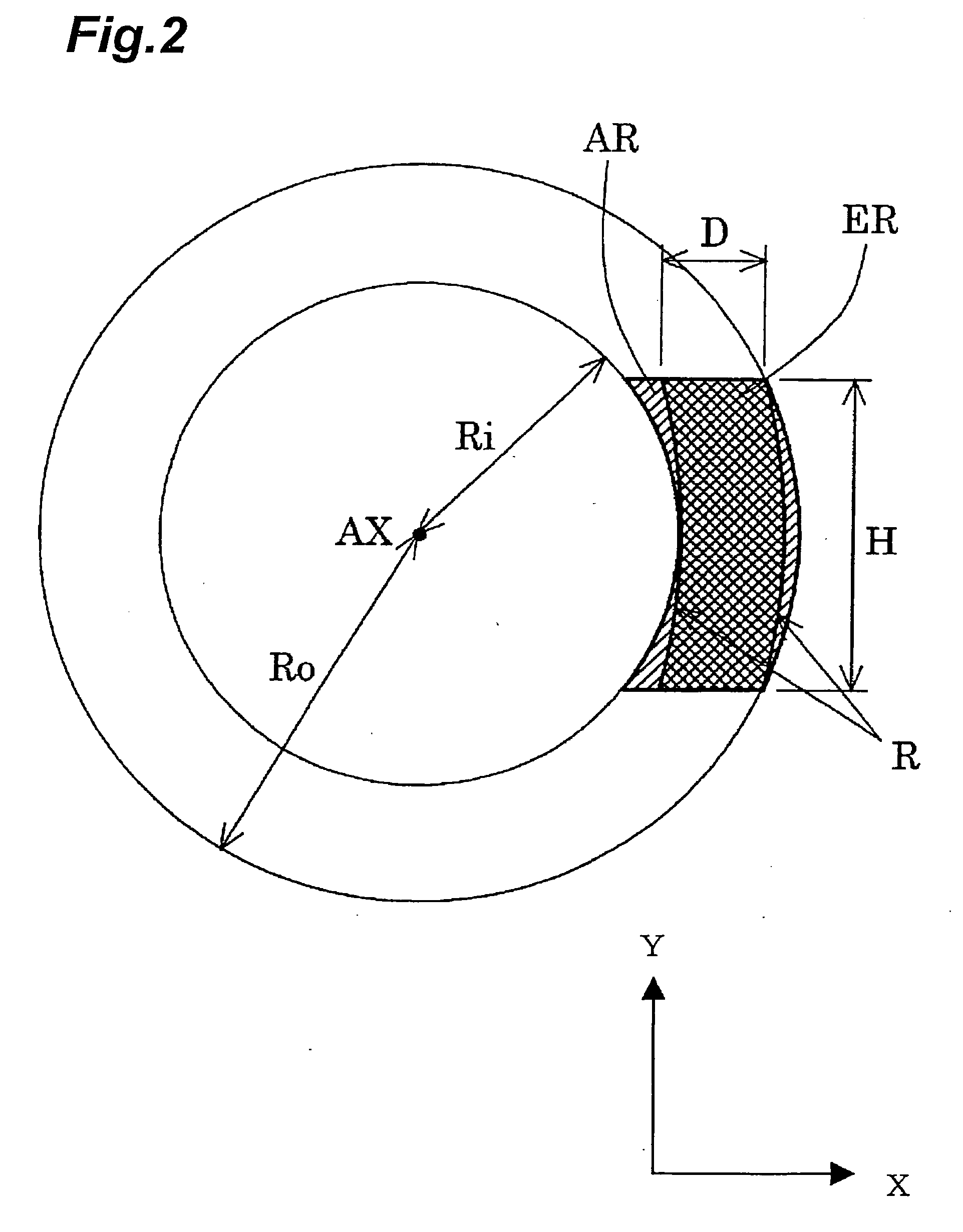
[0218] Image-side NA: 1.20 [0219] Exposure area: A=14 mm B=18 mm H=26.0 mm C=4 mm [0220] Imaging magnification: ¼[0221] Center wavelength: 193.306 nm [0222] Refractive index of silica: 1.5603261 [0223] Refractive index of fluorite: 1.5014548 [0224] Refractive index-of liquid 1: 1.43664 [0225] Dispersion of silica (dn / dλ): −1.591E−6 / pm [0226] Dispersion of fluorite (dn / dλ): −0.980E−6 / pm [0227] Dispersion of liquid 1 (dn / dλ): −2.6E−6 / pm

[0228] Values corresponding to Condition Ma=374.65 mm L=1400 mm

TABLE 3(Specifications of Optical Members)#2#3#4#1 ∞50.0000 1:∞8.0000#5 2:∞33.0000 3:ASP125.0422#5 4:−163.965211.0000 5:355.3161760.7391#5 6:−261.841151.0000 7:277.3335429.0109#5 8:ASP2224.5285 9:−176.6187220.0000#510:−515.6071010.461411:ASP3−10.4614#612:−515.60710−20.0000#513:−176.61872−204.528514:ASP4518.3706#615:−517.39842−241.3807#616:−652.07494171.3807#617:ASP520.0000#518:171.5938241.474319:−245.9452520.0000#520:ASP695.141521:ASP728.3218#522:−273.722611.000023:578.3...


PUM

PropertyMeasurementUnit
wavelengthaaaaaaaaaa
Maaaaaaaaaaa
wavelengthaaaaaaaaaa

Abstract

A catadioptric projection optical system for forming a reduced image of a first surface (R) on a second surface (W) is a relatively compact projection optical system having excellent imaging performance as well corrected for various aberrations, such as chromatic aberration and curvature of field, and being capable of securing a large effective image-side numerical aperture while suitably suppressing reflection loss on optical surfaces. The projection optical system comprises at least two reflecting mirrors (CM1, CM2), and a boundary lens (Lb) whose surface on the first surface side has a positive refracting power, and an optical path between the boundary lens and the second surface is filled with a medium (Lm) having a refractive index larger than 1.1. Every transmitting member and every reflecting member with a refracting power forming the projection optical system are arranged along a single optical axis (AX) and the projection optical system has an effective imaging area of a predetermined shape not including the optical axis.

Description

CROSS-REFERENCE TO RELATED APPLICATIONS [0001] This is a continuation of U.S. patent application Ser. No. 11 / 266,288 filed Nov. 4, 2005, which in turn is a continuation-in-part application of application serial no. PCT / JP2004 / 006417 filed on May 6, 2004. application Ser. No. 11 / 266,288 also claims a priority of the Provisional Application No. 60 / 721,582 filed on Sep. 29, 2005. The disclosures of these prior applications are incorporated herein by reference in their entirities. [0002] 1. Field of the Invention [0003] The present invention relates to a catadioptric projection optical system, exposure apparatus, and exposure method and, more particularly, to a high-resolution catadioptric projection optical system suitable for exposure apparatus used in production of semiconductor devices, liquid-crystal display devices, etc. by photolithography. [0004] 2. Related Background Art [0005] The photolithography for production of the semiconductor devices and others is implemented using a pr...

Claims


Application Information

Patent Timeline
Patent Type & Authority Applications(United States)
IPC IPC(8): G03C5/00
CPCG03F7/70225G03F7/70341G02B17/0844H01L21/027G02B9/34G03F7/7015
Inventor OMURA, YASUHIRO
Owner NIKON CORP
Learn More