Hybrid power supply

Inactive Publication Date: 2006-05-02
DURACELL U S OPERATIONS
View PDF54 Cites 27 Cited by
  • Summary
  • Abstract
  • Description
  • Claims
  • Application Information

AI Technical Summary

Benefits of technology

[0006]One or more aspects of the invention may include one or more of the following advantages.
[0007]The circuit can take advantage of charging voltage characteristics of Li− ion or Li− polymer rechargeable batteries. For example, the charge voltage of Li− ion batteries is conveniently related to their state of charge over a wide range. This allows the circuit to produce an output voltage from the DC / DC converter 12 at a level that corresponds to a desired state of charge. The circuit does not fully charge the rechargeable battery, sacrificing a percentage of the maximum continuous runtime of the device. But, the non-fully charged arrangement provides the following advantages. The circuit provides a higher energy efficiency of the rechargeable battery. At the end of charge of a rechargeable battery heat losses are produced. By avoiding maximum charge such losses are avoided. Also the rechargeable battery has a lower self-discharge rate (because of a lower charging voltage). In addition, there is minimization in damage from long-term storage. If the rechargeable battery is stored at full charge, the Li− ion battery will permanently lose part of its capacity. Also the circuit minimizes the need for a charge controller and protection circuit.
[0008]The circuit also loosens accuracy requirements for the DC / DC converter circuit. Li− ion chargers have typically better than 0.5% accuracy in the output voltage. This typically requires a second charging device after the DC / DC converter. Without fully charging the Li− ion cell allows for a + / − voltage tolerance allowing use of simple and inexpensive DC / DC converters. The circuit allows for a narrow voltage range at the device power supply terminal (which makes the device internal voltage regulation more efficient). The circuit automatically compensates for the amount of energy used from the rechargeable battery and provides a circuit having a very low quiescent current characteristic. The circuit efficiently uses the primary battery energy, has low EMI levels and can be integrated into existing Li− ion powered devices

Problems solved by technology

While primary batteries have a greater energy density, their internal resistance is larger, and primary batteries are less suitable in high drain (>0.2 C rate of discharge) electronic devices.
Rechargeable batteries can handle large loads but do not have sufficient energy capacity for many applications.

Method used


Image

  • Hybrid power supply
  • Hybrid power supply
  • Hybrid power supply

Examples


Embodiment Construction

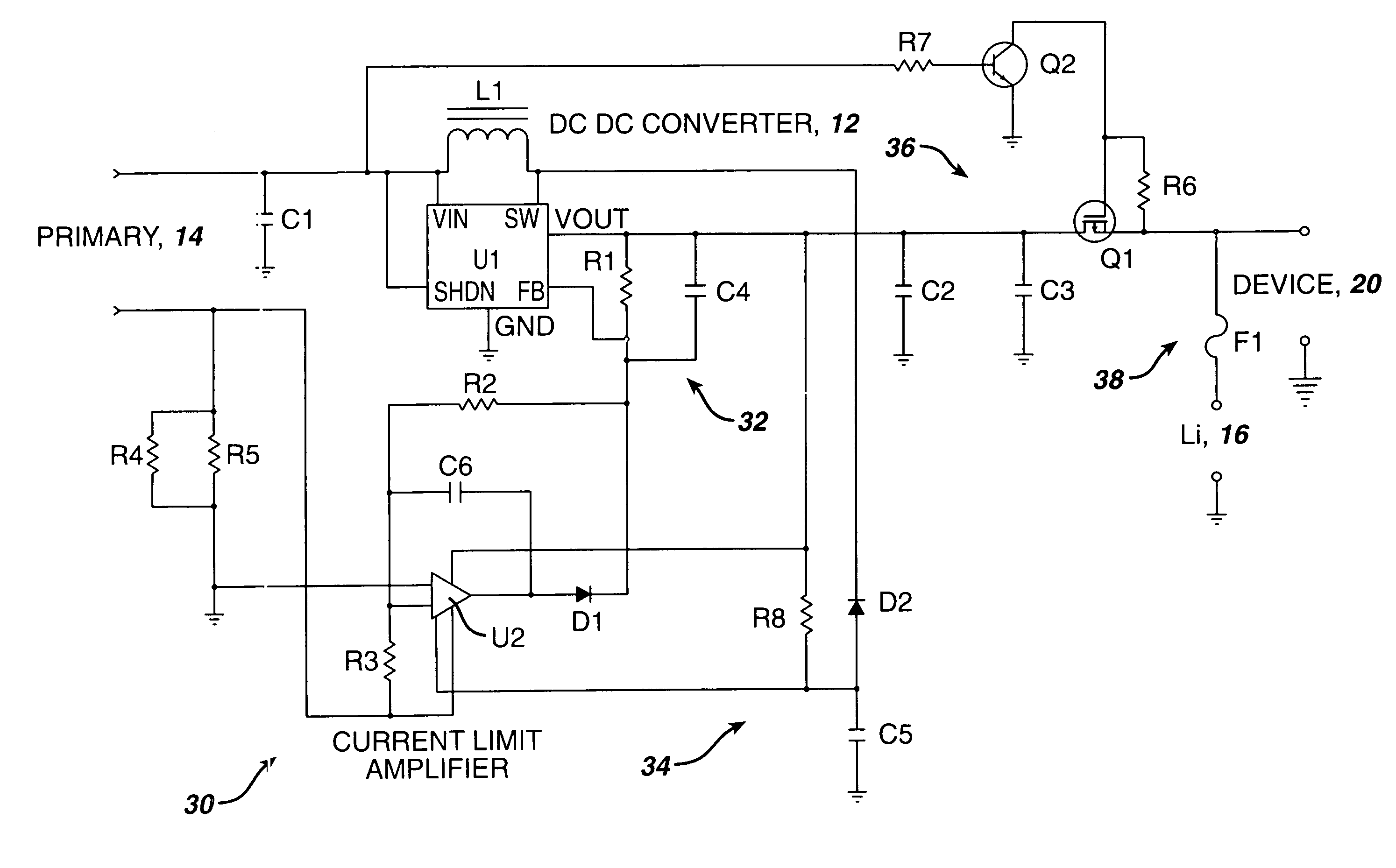
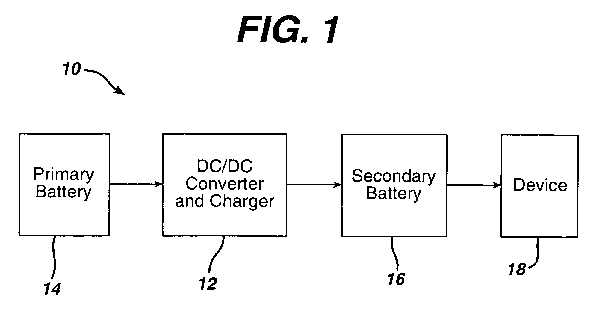
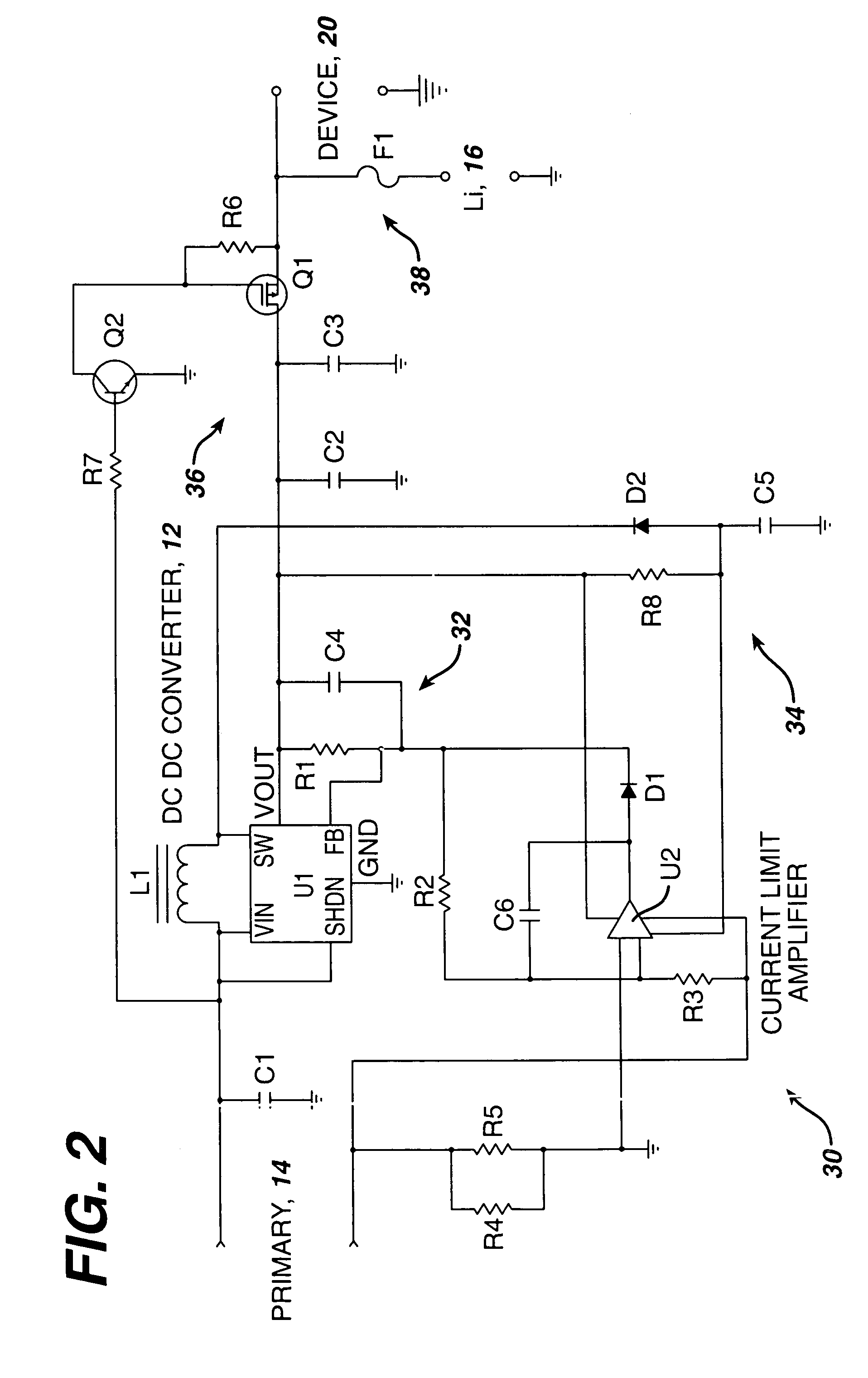
[0013]Referring to FIG. 1, a hybrid power supply 10 includes a switching type DC / DC boost type converter 12 that receives energy from a primary cell 14 and delivers the energy to a secondary, e.g., rechargeable cell 16. The rechargeable cell 16 delivers power, as needed, to the device 20. The device 20 can be any type of electronic device, especially a portable device such as a wireless device, e.g., a cell phone, personal digital assistant, digital camera, and so forth. The switching type DC / DC boost type converter 12 is configured to provide a fixed output voltage that is less than the charging voltage of the rechargeable cell 16, and is current limited to a portion of the charging current of the rechargeable cell. In this configuration, the switching type DC / DC boost type converter 12 acts also as a charger for the secondary battery. The rechargeable cell 16 can be a rechargeable Li− Ion type. Preferred examples include a Li− Ion or Li− Polymer rechargeable cell. These rechargeab...


PUM


Abstract

A hybrid power supply includes a switching type DC / DC boost type converter that receives energy from a primary battery cell and is arranged to deliver the energy to a rechargeable cell, set to provide a fixed output voltage that is less than the full charge voltage of the rechargeable cell. The hybrid power supply includes a circuit including a primary battery current control that senses primary battery current, and controls in part operation of the converter to provide constant current discharge on the primary battery side of the hybrid power supply.

Description

BACKGROUND[0001]This invention relates to powering of portable electronic devices.[0002]Portable electronic devices are normally powered with either a primary or a rechargeable battery. Growth in the portable electronic device market, as well as, changes in usage patterns, has provided opportunities for the integration of both primary and rechargeable sources of power to power an electronic device. While primary batteries have a greater energy density, their internal resistance is larger, and primary batteries are less suitable in high drain (>0.2 C rate of discharge) electronic devices. Rechargeable batteries can handle large loads but do not have sufficient energy capacity for many applications.SUMMARY[0003]According to an aspect of the invention, a hybrid power supply includes a switching type DC / DC boost type converter that receives energy from a primary battery cell and is arranged to deliver the energy to a rechargeable cell, set to provide a fixed output voltage that is le...

Claims


Application Information

Patent Timeline
IPC IPC(8): H02J1/16H01M10/44H02J7/00H02M3/155
CPCH02J7/0054H02J7/342
Inventor BOURILKOV, JORDAN T.KLEIN, DAVID N.ROTONDO, JOHN
Owner DURACELL U S OPERATIONS
Why Eureka
Try Eureka