
Seal and pressure relief for steam injection heater

a steam injection heater and pressure relief technology, which is applied in the direction of multiple way valves, machines/engines, combustible gas purification/modification, etc., can solve the problems of unwanted vibration in the heating system, and achieve the effect of preventing hot and cold spots and discharging heat more efficiently

Active Publication Date: 2006-04-11
HYDRO THERMAL
View PDF28 Cites 15 Cited by
  • Summary
  • Abstract
  • Description
  • Claims
  • Application Information

AI Technical Summary

Benefits of technology

[0008]The invention is a direct contact steam injection heater in which steam is introduced into a flow of stock that is flowing axially through a pipe. The heater is installed in line and allows continued axial flow of the stock so the stock flow is not required to negotiate sharp turns when passing through the heater. That is, the heater includes a heater body having a flowing stock inlet and a heated stock discharge outlet that are aligned to provide axial flow through the pipe and the heater body. Full pressure steam is introduced into the stock through a Mach diffuser that is mounted transverse to the axial flow through the heater body. The Mach diffuser has a plurality of steam diffusion holes through which small jets of steam are injected into the flowing stock. The small steam jets break apart easily in viscous slurries and disperse before the steam has a chance to conglomerate into large bubbles that can create “steam hammers” and lead to unwanted vibration within the heating system. Furthermore, small steam bubbles dissipate heat more efficiently and thereby prevent hot and cold spots in the flowing stock.

Problems solved by technology

The small steam jets break apart easily in viscous slurries and disperse before the steam has a chance to conglomerate into large bubbles that can create “steam hammers” and lead to unwanted vibration within the heating system.

Method used


Image

  • Seal and pressure relief for steam injection heater
  • Seal and pressure relief for steam injection heater
  • Seal and pressure relief for steam injection heater

Examples


Embodiment Construction

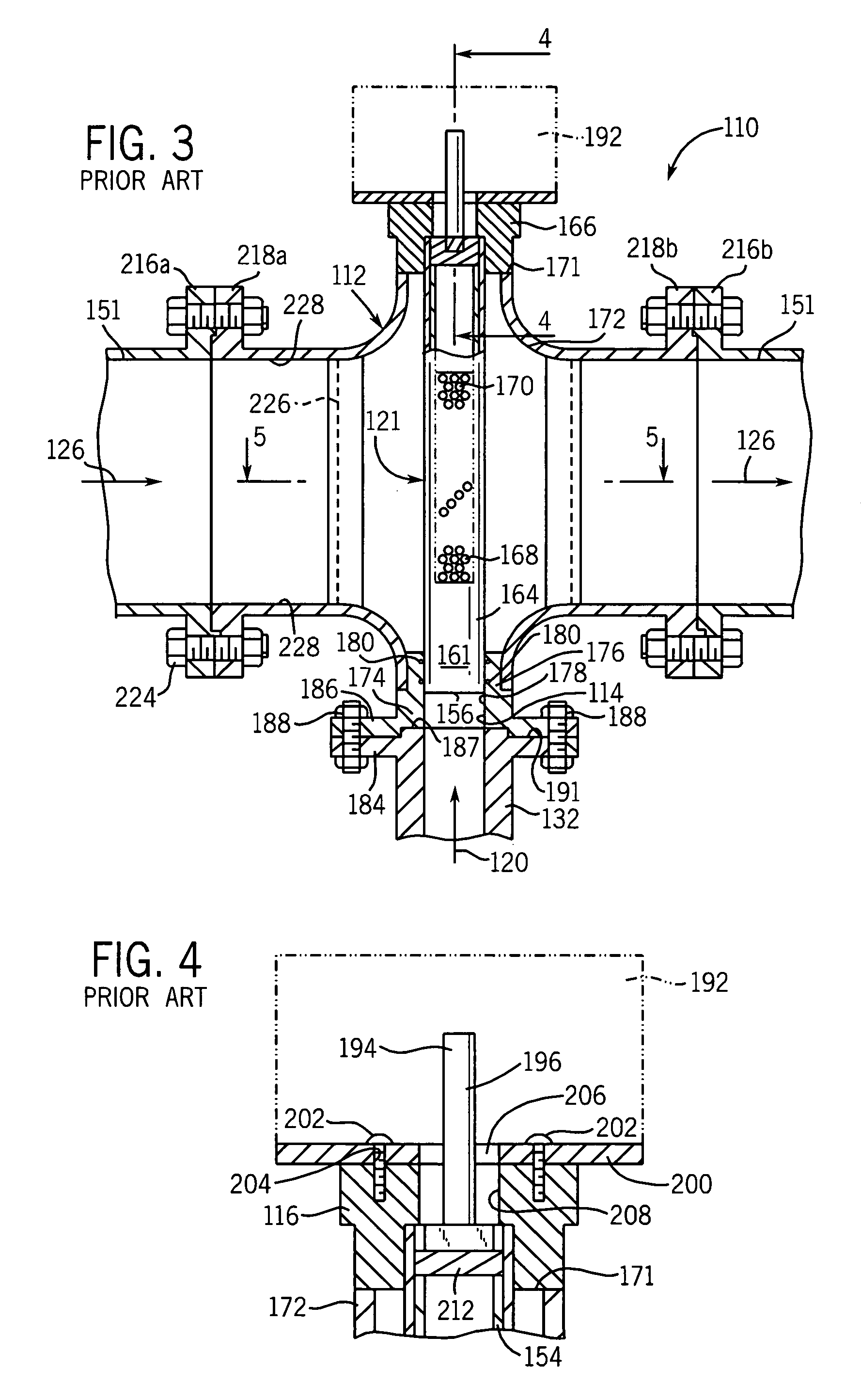
[0037]The invention as illustrated in FIGS. 1–12 is designed to accommodate large flows of slurries or other viscous liquids containing materials that tend to flocculate, such as suspended fibrous or particulate matter. In accordance with the invention, the heater 110 has a Mach diffuser 121 that is placed transversely in the heater body 112. The heater body 112 is connected in line with a stock supply pipe.

[0038]As shown in FIGS. 1–3, steam 120 flows into heater 110 through a steam inlet 114, and into an internal region 152 (FIG. 5) defined by a cover 154 located within the Mach diffuser 121. Steam 120 enters internal region 152 through an opening 156 located near steam pipe 132. Cover 154 is a cylindrical wall having a closed end 158 and an open end 160, FIG. 2. Steam is supplied through the cover 154 via openings 162 (only one opening 162 is shown in FIG. 2, the other opening is directly opposite of the opening 162 that is shown) at essentially the full steam pressure available a...


PUM

PropertyMeasurementUnit
Massaaaaaaaaaa
Pressureaaaaaaaaaa
Flow rateaaaaaaaaaa

Abstract

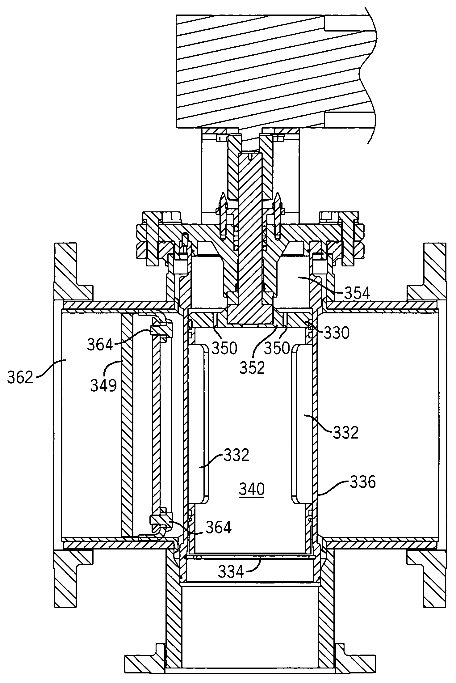
A direct contact steam injection heater is placed directly in line with a flow of stock through a pipe. The steam injection heater includes a Mach diffuser having a plurality of steam diffusion holes and an adjustable steam-plug cover that is positioned within a stationary diffuser tube to modulate the amount of steam added to the flowing stock by exposing a desired number of steam diffusion holes. The steam tube assembly includes an O-ring that forms a seal along the inner wall of the diffuser tube to prevent the flow of stock into the steam tube assembly when steam pressure is not present. Select areas of the steam injection heater, including the deflection plate, diffuser tube and heater body inner wall are coated with a wear coating such as tungsten carbide. Further, a pair of pressure ports are formed in the steam-plug cover to equalize the pressure between the open interior of the steam-plug cover to further facilitate rotation of the steam-plug cover.

Description

CROSS-REFERENCE TO RELATED APPLICATION[0001]The present application is based on and claims priority to U.S. Provisional Patent Application No. 60 / 458,522 filed Mar. 28, 2003.BACKGROUND OF THE INVENTION[0002]The present invention relates to direct contact steam injection heaters that use full pressure steam. More particularly, the invention relates to a direct contact steam injection heater for heating certain types of slurries that contain abrasive material.[0003]In direct contact steam injection heaters, steam is directly mixed into a flowing stock (e.g. liquid or slurry) being heated. Direct contact steam injection heaters are very effective at transferring heat energy to the flowing stock. They provide rapid heat transfer with virtually no heat loss to the atmosphere, and also transfer both the latent and the available sensible heat of the steam to the liquid slurry.[0004]The present invention was developed during ongoing developmental efforts by the assignee in the field of dire...

Claims


Application Information

Patent Timeline
IPC IPC(8): B01F3/04B01F5/04F16K11/085F28C3/06F28C3/08
CPCB01F5/0451B01F5/0453B01F5/0463F16K11/085F28C3/06F28C3/08B01F15/0429Y10S261/10B01F25/3132B01F25/31331B01F25/3131B01F35/718051B01F35/833
Inventor CINCOTTA, BRUCE A.BERTSCH, MATTHEW
Owner HYDRO THERMAL
Learn More