
Main-steam-flow-based steam turbine sliding pressure optimization control method

A technology of main steam flow and control method, which is applied in the control field of steam turbine sliding pressure optimization, can solve the problems of large error in main steam flow and difficult practical application, and achieves the effect of improving operating economy and tapping energy-saving potential.

Active Publication Date: 2015-12-30
STATE GRID HENAN ELECTRIC POWER ELECTRIC POWER SCI RES INST +2
View PDF4 Cites 36 Cited by
  • Summary
  • Abstract
  • Description
  • Claims
  • Application Information

AI Technical Summary

Problems solved by technology

However, due to the large error of the main steam flow at the site, the theoretical sliding pressure curve based on the main steam flow given by the manufacturer is difficult to be applied in practice.

Method used


Image

  • Main-steam-flow-based steam turbine sliding pressure optimization control method
  • Main-steam-flow-based steam turbine sliding pressure optimization control method
  • Main-steam-flow-based steam turbine sliding pressure optimization control method

Examples


Embodiment 1

[0063] Combine below figure 2 , image 3 This embodiment will be specifically described.

[0064] The process of applying this method to a 600MW supercritical steam turbine unit to obtain the main steam flow calculation formula and sliding pressure optimization curve is as follows:

[0065] Under the rated load of 600MW, the steam turbine heat rate test is carried out according to the ASME standard. According to the test data, the main steam flow calculation formula is obtained as:

[0066] G = 1251.089 × p 1 2 - p 2 2 0.01324 × P d × t d - ...


PUM


Abstract

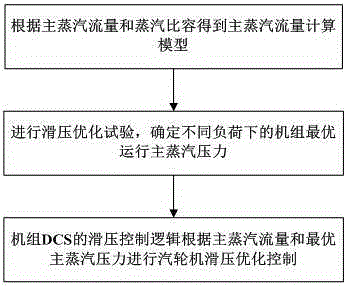
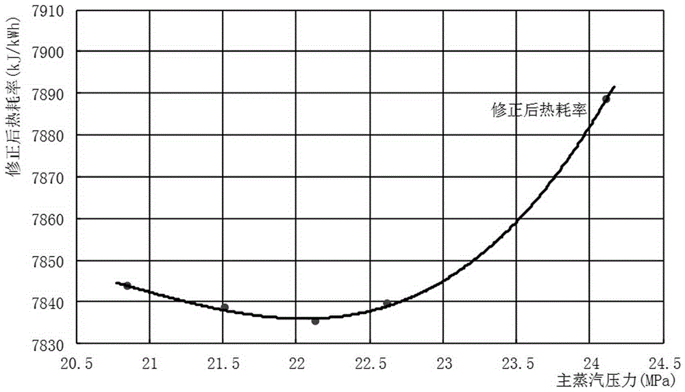
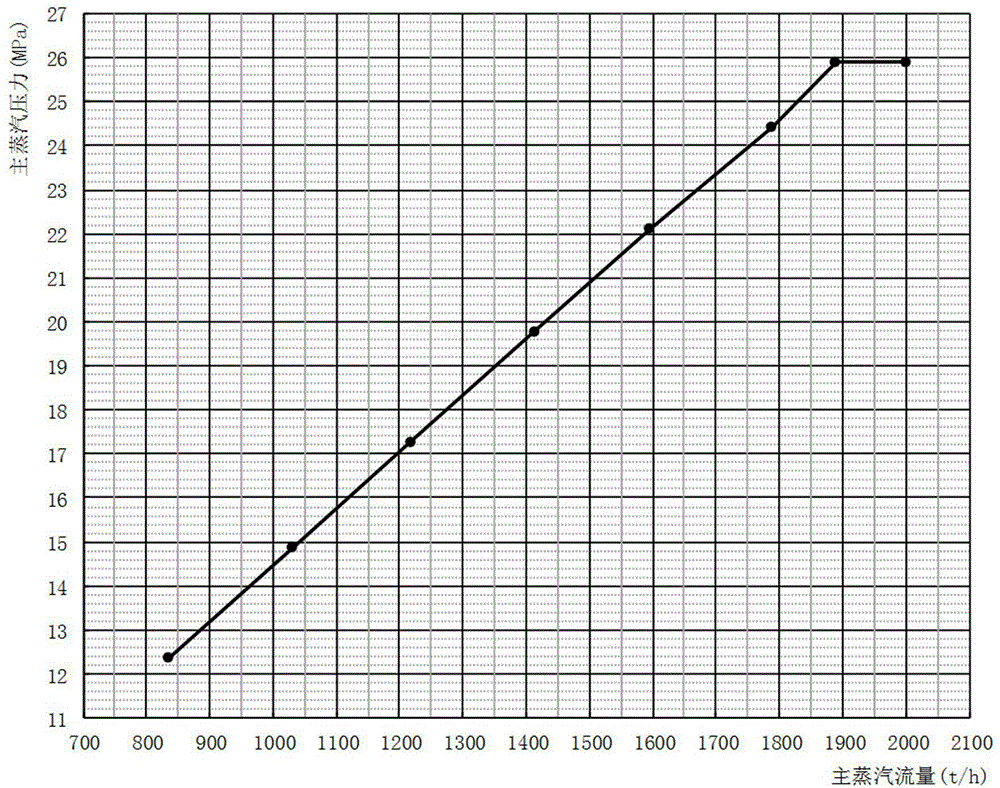
The invention discloses a main-steam-flow-based steam turbine sliding pressure optimization control method which comprises the following steps: 1. obtaining a main steam flow calculation model according to the main steam flow and steam specific volume; 2. carrying out sliding pressure optimization testing to determine the optimal operation main steam pressure of the set under different loads; and 3. carrying out steam turbine sliding pressure optimization control by set DCS sliding pressure control logic according to the main steam flow and optimal main steam pressure obtained by the formula (3) and formula (5). In order to solve the problem that the changes of back pressure, main reheated steam temperature, heat supply and other factors influence the economical efficiency of the set in the steam turbine sliding pressure operation process, the invention provides a main-steam-flow-based steam turbine sliding pressure optimization control method, so that the steam turbine can still keep the optimal operating mode when the influencing factors change, thereby further exploring the energy conservation potential of the set.

Description

technical field [0001] The invention belongs to the field of steam turbine control in thermal power plants, and in particular relates to a control method for steam turbine sliding pressure optimization based on main steam flow. Background technique [0002] With the rapid development of the national economy, the domestic electricity demand continues to grow. In order to increase the power generation capacity of a single machine, large-capacity units are increasing day by day, gradually replacing small-capacity units, resulting in an increasing grid capacity and a corresponding increase in the peak-to-valley difference. Large-capacity units also have to participate in peak-shaving operations frequently, and often operate with large-scale variable conditions between 50% and 100% load. In order to deal with the problem of poor economy when the load of the unit changes, the daily operation of large thermal power generating units often adopts the compound sliding pressure operat...

Claims


Application Information

Patent Timeline
IPC IPC(8): F01D17/00G06F19/00
Inventor 范鑫刘静宇石峰王建华张清甫崔皓程
Owner STATE GRID HENAN ELECTRIC POWER ELECTRIC POWER SCI RES INST
Learn More