
Data synchronization detection method, information recording method, and information reproduction method

Inactive Publication Date: 2006-03-28
HITACHI VIDEO & INFORMATION SYST +1
View PDF5 Cites 17 Cited by
  • Summary
  • Abstract
  • Description
  • Claims
  • Application Information

AI Technical Summary

Benefits of technology

[0008]With the conventional method, data synchronization can be more reliably performed by providing a data synchronization signal at a plurality of locations. However, the data synchronization signal is not in itself information of the user of the magnetic disc device that must be stored on the magnetic disc device. Consequently, increasing the portions where the data synchronization signal is provided lowers the so-called format efficiency, which expresses the efficiency of utilization of the recording medium by the data.

Problems solved by technology

However, the data synchronization signal is not in itself information of the user of the magnetic disc device that must be stored on the magnetic disc device.
Consequently, increasing the portions where the data synchronization signal is provided lowers the so-called format efficiency, which expresses the efficiency of utilization of the recording medium by the data.
Also, as the recording density of information of the magnetic disc device increases, situations which are undesirable in regard to data synchronization may be imagined, such as instances where the probability of occurrence of TA becomes high, instances where the rate of occurrence of defects of the recording medium (portions where correct recording / reproduction of circumstances can be coped with by improving the data identification performance by improvements in signal processing of the data or by improvements in data error correction capability by using error correction code.
On the other hand, in regard to the data synchronization signal, in order to maintain or improve the detection rate of the data synchronization signal, consideration may be given to increasing the regions of the data synchronization signal; however, this tends to lower the format efficiency, as mentioned above.
As described above, if there is an error in the detection of a data synchronization signal at the head of the data (it is not detected in the correct position or is detected in an erroneous position), there is the technical problem that this constitutes not merely a detection error in the data synchronization signal but also results in error in all the following several hundred bytes of code demodulation, thereby severely lowering the overall error rate.

Method used


Image

  • Data synchronization detection method, information recording method, and information reproduction method
  • Data synchronization detection method, information recording method, and information reproduction method
  • Data synchronization detection method, information recording method, and information reproduction method

Examples


Embodiment Construction

[0044]An embodiment of the present invention is described in detail below with reference to drawings.

[0045]FIG. 18 is a view illustrating a format etc according to the present invention. On magnetic disc 211 on which the information is recorded, there are provided concentric circular tracks 21; in tracks 21 there are sectors 22 constituting the information storage / reproduction units. A sector 22 comprises PLO_SYNC 91, DATA 93, ECC 94 and GAP 95. In this case, the conventional data synchronization signal is absent, and PLO_SYNC 91 and DATA 93 are adjacent. The bottom portion of this Figure illustrates an example of the data reproduction waveform form the reproduction head. This is the reproduction waveform 23-1 of the front portion of sector 22 from PLO_SYNC 91 to DATA 93 and the reproduction waveform 23-2 of the rear portion of sector 22 from ECC 94 to GAP 95. Although, to facilitate understanding, the reproduction waveform 23-2 which is here illustrated is a PLO_SYNC form waveform ...


PUM


Abstract

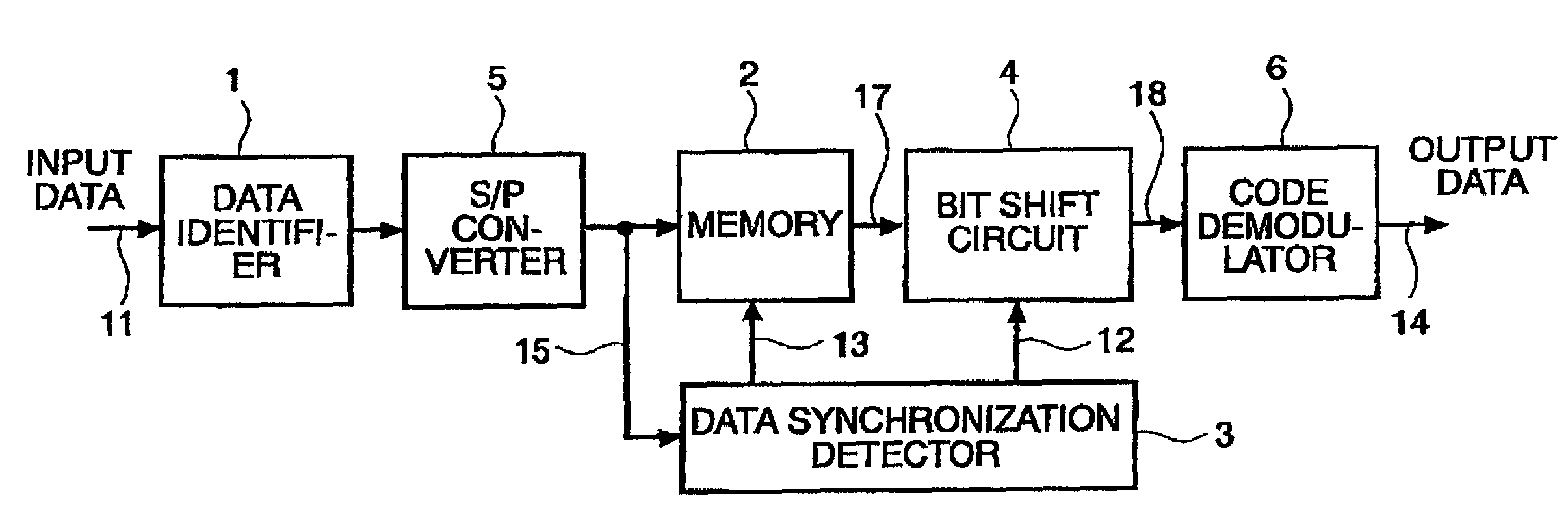
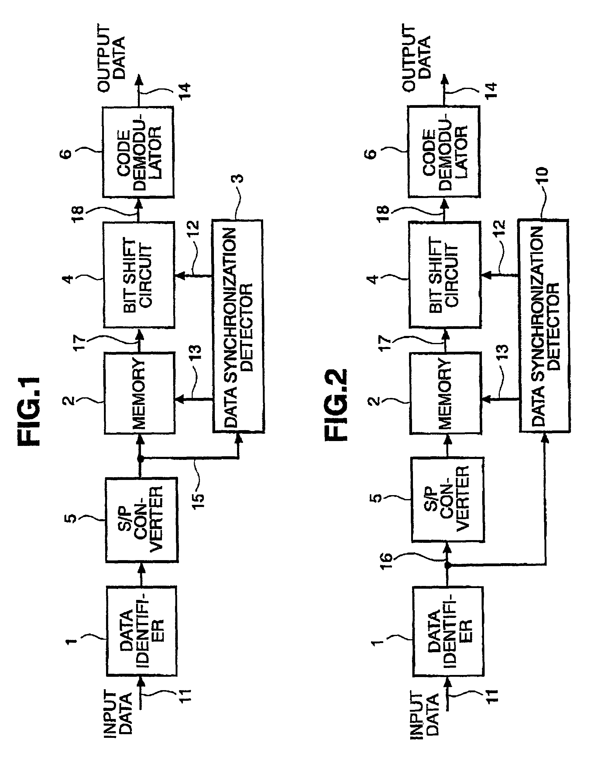
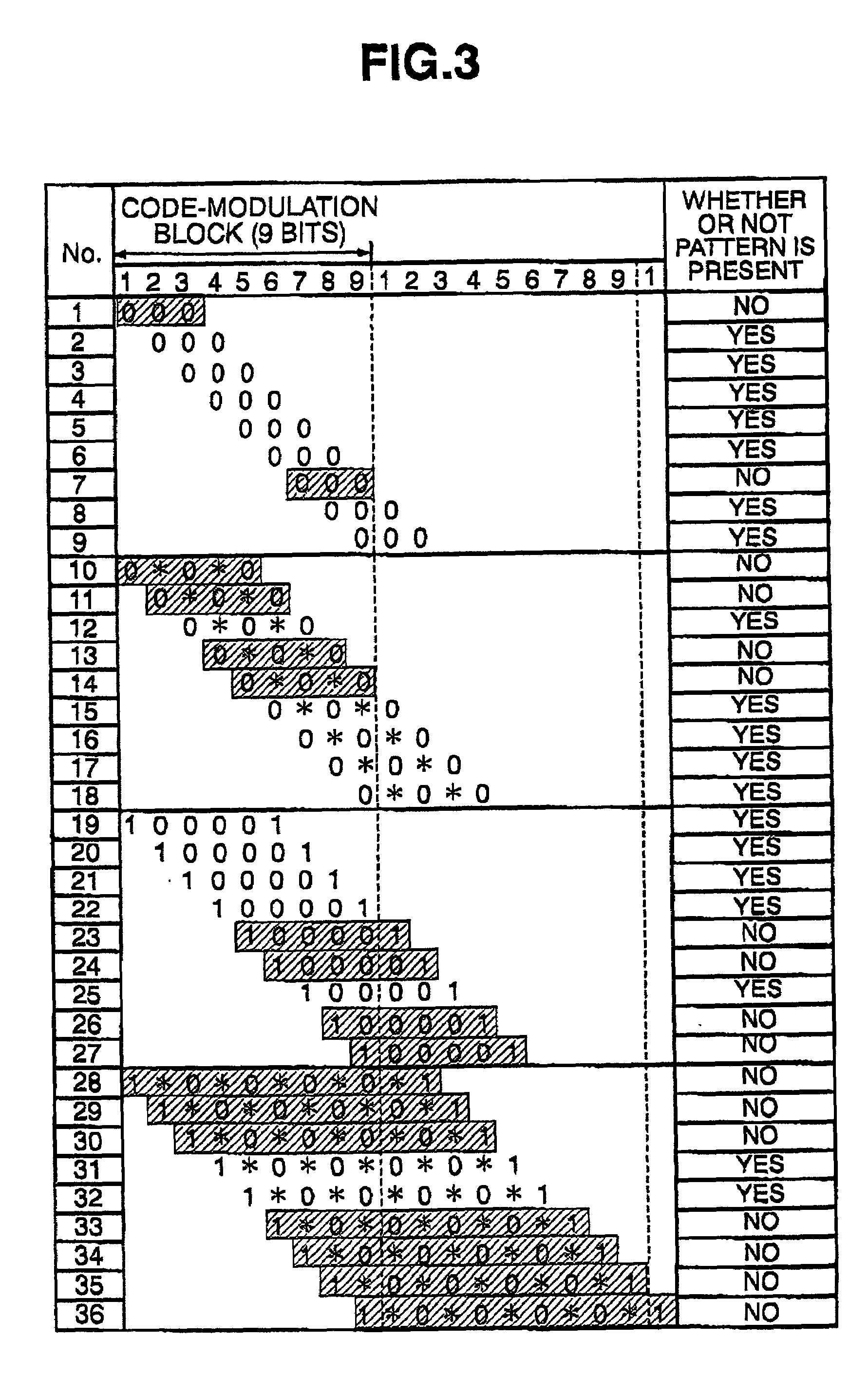
Data synchronization detection is provided between data identification and code demodulation in a data reproduction system, which performs data synchronization detection using code-modulated data. A specified bit pattern generated in a data codeword is calculated in each phase (bit), using a specified bit sequence pattern that is not generated in a specified phase of the data codeword. For example, a specified bit sequence pattern is generated only in a specified phase of the codeword). The positions of the data codeword partitions are thereby identified. Scrambling is then applied to the write data as required in order to ensure accurate synchronization detection.

Description

BACKGROUND OF THE INVENTION[0001]The present invention relates to information recording and reproduction technology and in particular relates to techniques that are effective in application to data synchronization detection etc of reproduced data in digital data recording / reproduction systems. In more detail, it relates to a data synchronization detection technique in which the information recording medium format efficiency is by improving data synchronization and detection performance without employing the conventional data synchronization signal pattern (that is “no Sync byte” or “Sync byte less”), by implementing data synchronization by means of the frequency of occurrence of a specified pattern in the reproduced data.[0002]Conventional data synchronization detection is described below with reference to the drawings.[0003]The conventional method is described taking a magnetic disc device as an example. FIG. 25 is an example of the recording format of a magnetic disc device. The d...

Claims


Application Information

Patent Timeline
IPC IPC(8): G06F11/00G11B20/10G11B20/14G11B20/12G11B27/30H04L1/00H04L7/00H04L7/02H04L7/04H04L7/08
CPCG11B20/10G11B20/12G11B27/3027H04L1/0047G11B2220/20H04L7/046H04L1/0075H04L7/0066H04L1/0046
Inventor WATANABE, YOSHIJUITO, YASUYUKI
Owner HITACHI VIDEO & INFORMATION SYST
Learn More