
Superconducting magnet coil support structure

support structure technology, applied in the direction of superconducting magnets/coils, instruments, magnetic bodies, etc., can solve the problems of inability to assemble a tooling large enough to accommodate a superconducting magnet coil support structure, inability to manufacture tools, and inapplicability of techniques, etc., to achieve accurate coil placement, reduce fabrication costs, and increase accuracy

Inactive Publication Date: 2006-03-21
GE MEDICAL SYST GLOBAL TECH CO LLC
View PDF4 Cites 4 Cited by
  • Summary
  • Abstract
  • Description
  • Claims
  • Application Information

AI Technical Summary

Benefits of technology

[0012]It is therefore an advantage of the present invention to provide a method of fabricating a superconducting magnet coil support structure for a magnetic resonance imager (MRI) system that is adaptable for various non-standard geometries and dimensions of a superconducting magnet.
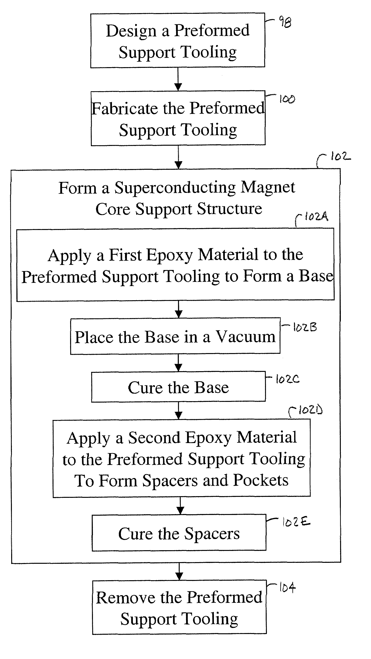
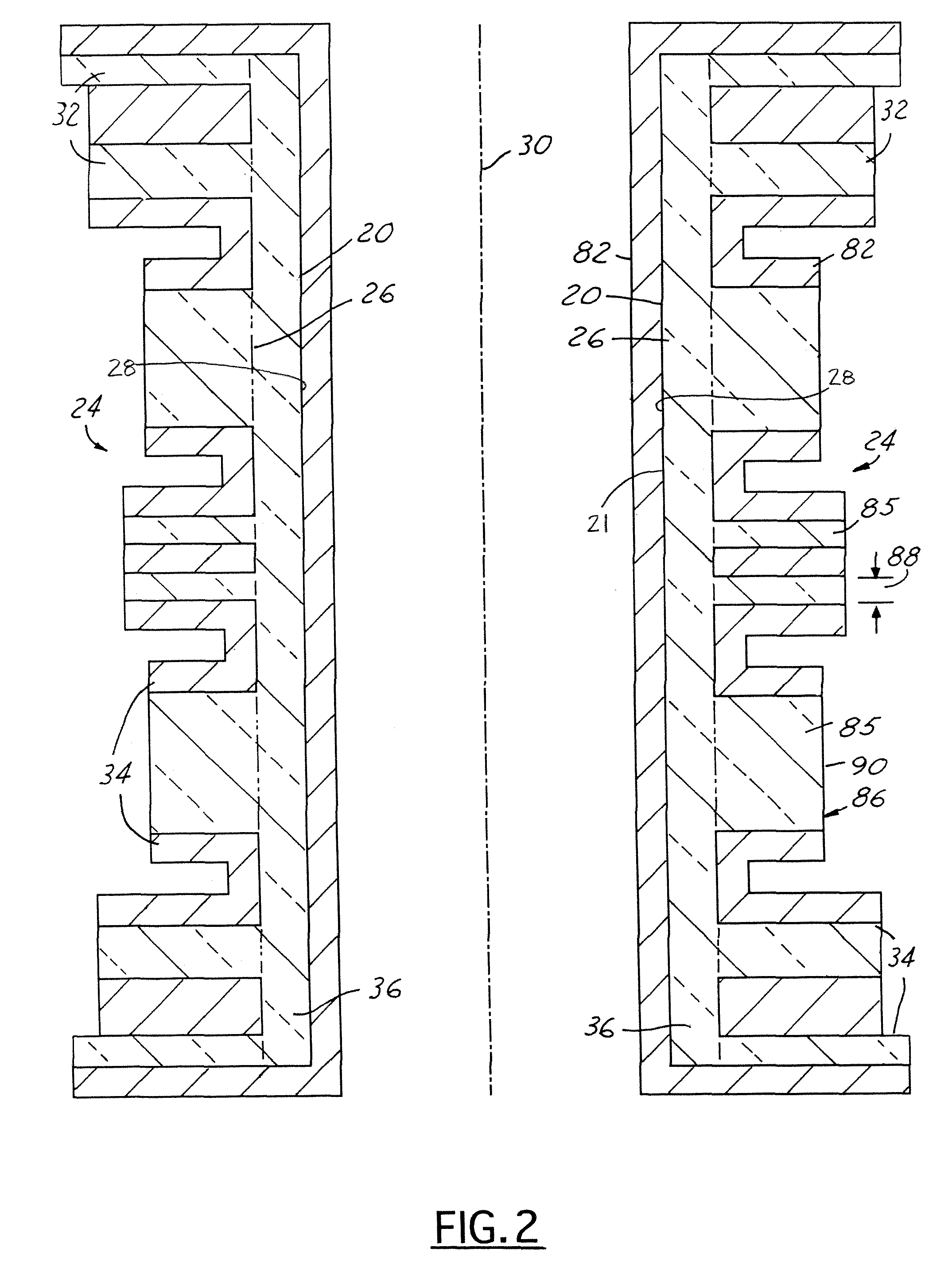
[0013]A superconducting magnet coil support structure is provided. The superconducting magnet coil support structure includes a solid body having an exterior side, an interior portion, and an interior side. The interior portion has a base that is formed of a first resin material. The exterior side has multiple spacers and multiple pockets with dimensions that correspond to dimensions of a superconducting magnet. The spacers are coupled to the base and are formed of a second resin material. The exterior side, the interior portion, and the interior side include varying width material. The present invention also provides a method of fabricating the same.
[0014]One advantage of the present invention is that it is versatile, since it may be applied to various MRI systems with varying superconducting magnet dimensions and geometries. The present invention provides increased accuracy, efficiency, and reduces costs in fabrication of a superconducting magnet coil support structure.
[0015]Another advantage of the invention, is its ability to vary the width of the fiberglass cloth during superconducting magnet coil support structure formation. By varying the fiberglass cloth width, the correct final dimensions of the superconducting magnet coil support structure are achieved and accurate coil placement is provided.
[0016]A further advantage of the present invention is that the preform support tooling used therein stabilizes the wound fiberglass cloth to create accurate windings of the fiberglass cloth. The preform support tooling also provides a restraint to prevent layer-to-layer separation, which can create weak areas in the superconducting magnet coil support structure. The tooling also allows for larger radial builds, that are not possible using the traditional wet winding process.

Problems solved by technology

When the superconducting magnet suddenly quits carrying a charge or current, quench forces result, causing the superconducting magnet coils to move.
Equipment utilized within these techniques is currently incapable of forming a tooling large enough to accommodate a superconducting magnet coil support structure.
Also, such techniques are simply impractical for the formation of a superconducting magnet coil support structure, since in doing so would result in a large amount of wasted material.
The non-standard dimensions are more difficult to cut out then the standard dimensions.
Thus, specialized tooling and equipment is necessary to continue using the traditional wet winding process, increasing time and expense involved therein.
Also, in order to efficiently and reliably utilize the specialized tooling and equipment, additional technician training time and expense would be incurred.
The difficulty level is sufficient and known to one skilled in the art, to cause the traditional process used to create the superconducting magnet coil support structure having non-standard dimensions to be infeasible and obsolete.
The traditional wet winding process is also unstable, inaccurate, and inefficient for the following reasons.
Extra time and expense is thus required to rework the superconducting magnet coil support structures.

Method used


Image

  • Superconducting magnet coil support structure
  • Superconducting magnet coil support structure
  • Superconducting magnet coil support structure

Examples


Embodiment Construction

[0021]The present invention is described herein with respect to an apparatus and a fabricating method for producing a superconducting magnet coil support structure. However, it will be understood that the following is capable of being adapted for various purposes and is not limited to the following applications; namely magnetic resonance imager (MRI) systems, magnetic resonance spectroscopy systems, and other applications that require use of a magnet support structure.

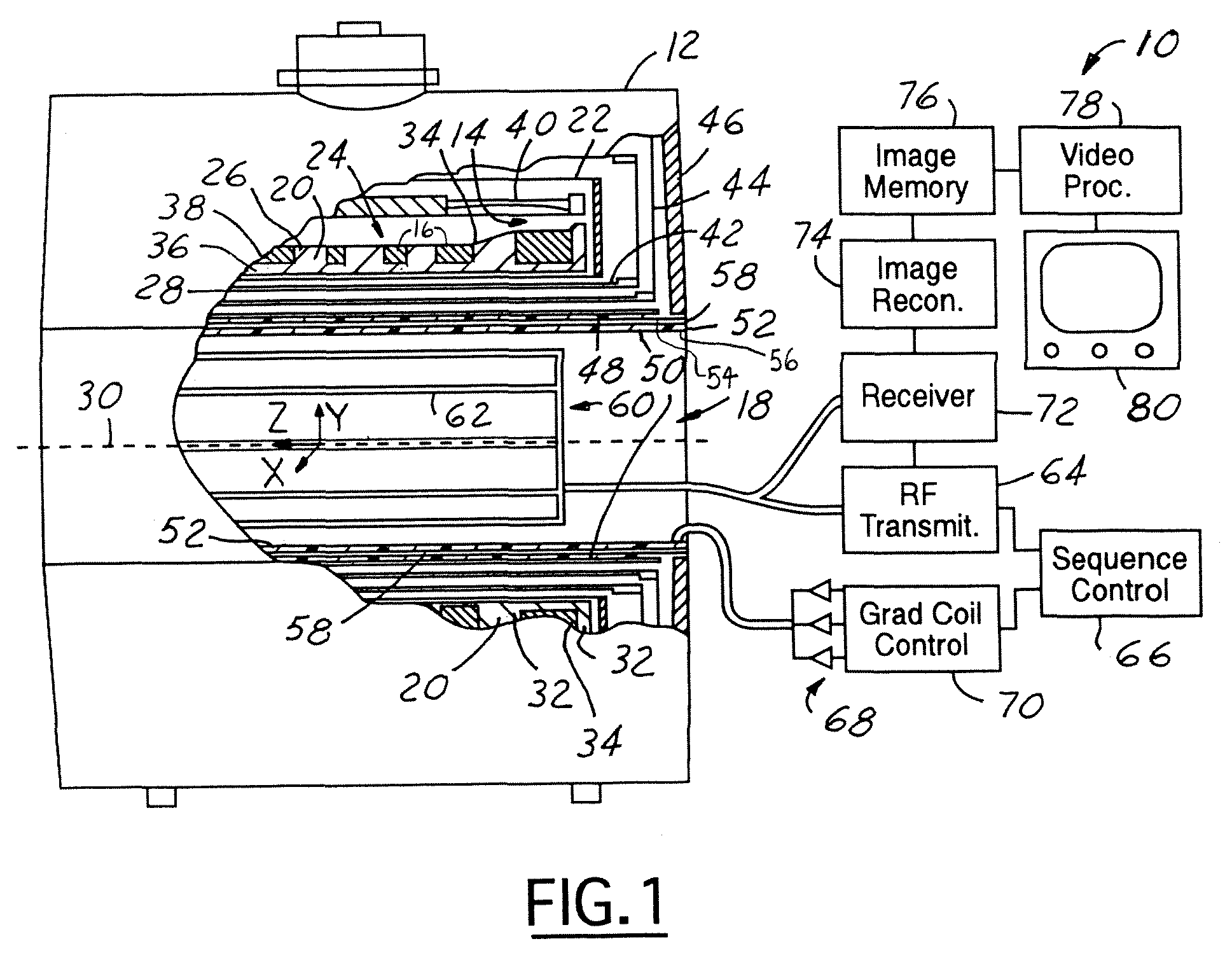
[0022]Referring now to FIG. 1, a block diagrammatic view of an MRI system 10. The MRI system 10 includes a static magnet structure 12 (a cylindrical structure) has a superconducting magnet 14 with multiple superconducting magnetic field coils 16, which generate a temporally constant magnetic field along a longitudinal axis (z-axis) of a central bore 18 (patient bore). The superconducting magnet coils 16 are supported by a superconducting magnet coil support structure 20 and received in a toroidal helium vessel or can 2...


PUM

PropertyMeasurementUnit
superconductingaaaaaaaaaa
dimensionsaaaaaaaaaa
widthsaaaaaaaaaa

Abstract

A superconducting magnet coil support structure (20) includes a solid body (21) having an exterior side (24), an interior portion (26), and an interior side (28). The interior portion has a base (36) that is formed of a first resin material. The exterior side (24) has multiple spacers (32) and multiple pockets (34) with dimensions that correspond to dimensions of a superconducting magnet (14). The spacers (32) are coupled to the base (36) and are formed of a second resin material. The exterior side (24), the interior portion (26), and the interior side (28) include varying width material.

Description

CROSS REFERENCE TO RELATED APPLICATIONS[0001]The present application is a continuation-in-part of U.S. patent application Ser. No. 09 / 681,888, filed on Jun. 20, 2001 now abandoned, entitled “SUPERCONDUCTING MAGNET COIL SUPPORT STRUCTURE”, which is incorporated by reference herein.BACKGROUND OF INVENTION[0002]The present invention relates generally to a superconducting magnet coil support structure. More particularly, the present invention relates to a method and apparatus for supporting a superconducting magnet in a Magnetic Resonance Imager (MRI) System.[0003]Current Magnetic Resonance Imager (MRI) systems include a superconducting magnet that generates a temporally constant primary magnetic field. The superconducting magnet is used in conjunction with a magnetic gradient coil assembly, which is sequentially pulsed to create a sequence of controlled gradients in the static magnetic field during a MRI data gathering sequence. The superconducting magnet and the magnetic gradient coil...

Claims


Application Information

Patent Timeline
Patent Type & Authority Patents(United States)
IPC IPC(8): H01L39/24H10N60/00G01R33/3815H01F6/06H01F41/04
CPCG01R33/3815H01F41/048H01F6/06Y10T29/49014B33Y80/00
Inventor ELGIN, II, STEPHEN R.ALLFORD, MICHAEL L.EGGLESTON, MICHAEL R.
Owner GE MEDICAL SYST GLOBAL TECH CO LLC
Learn More