Method and apparatus for assessing neural function by sparse stimuli
- Summary
- Abstract
- Description
- Claims
- Application Information
AI Technical Summary
Benefits of technology
Problems solved by technology
Method used
Image
Examples
example 1
Apparatus
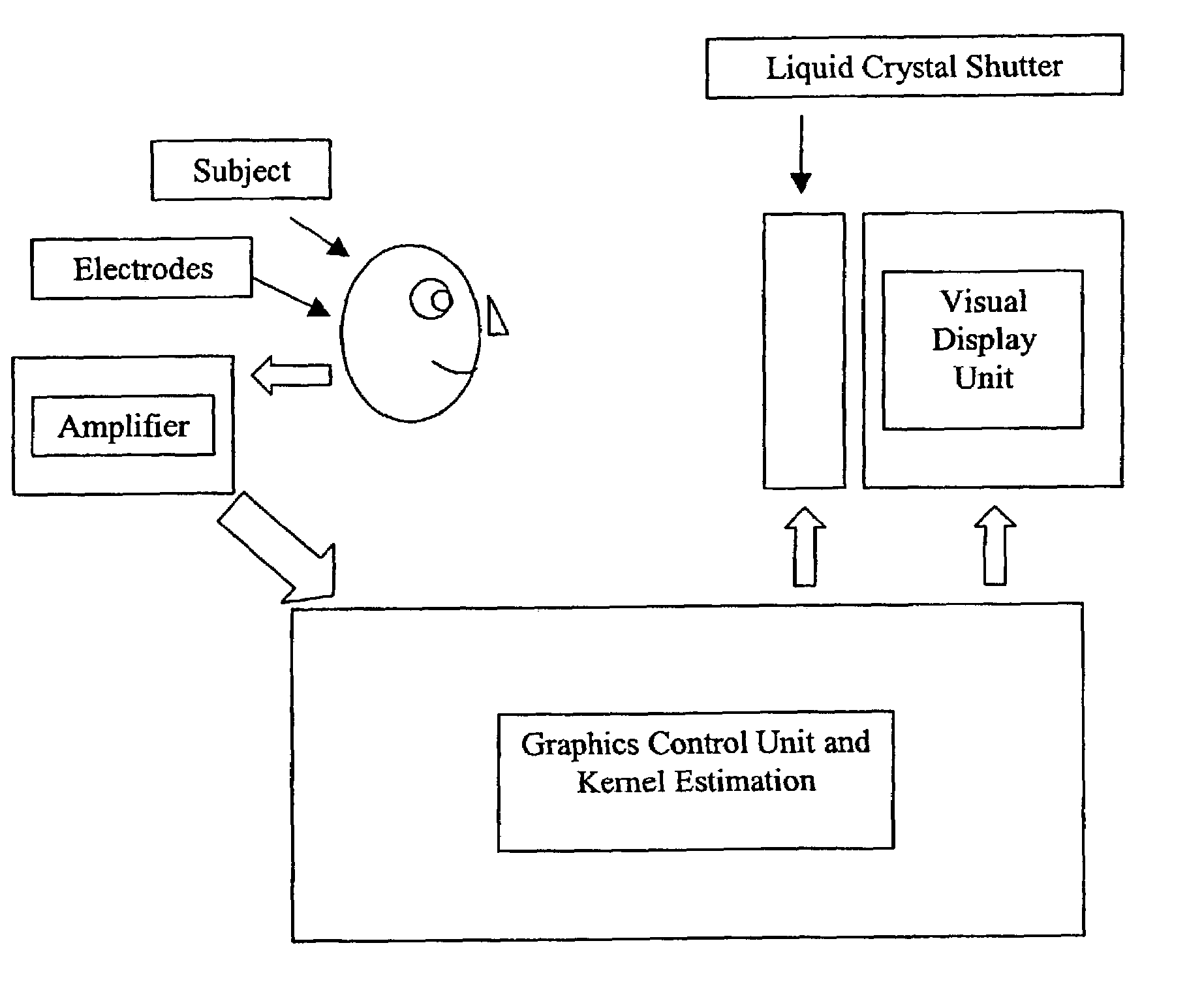
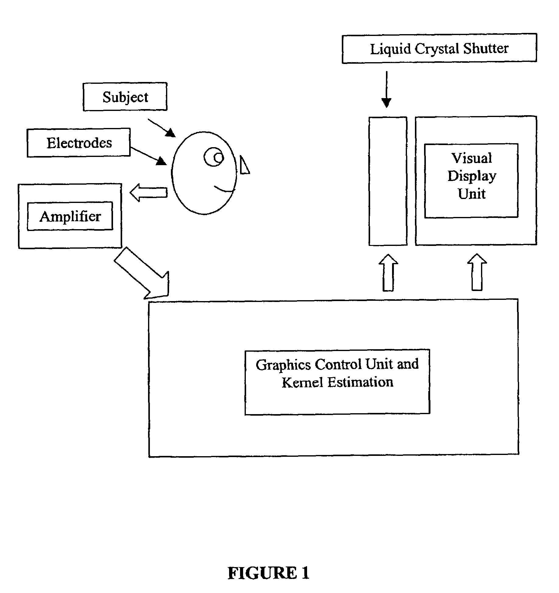
[0072]A schematic of the basic system components forming an embodiment of the apparatus of the present invention is shown in FIG. 1. The major components are an apparatus for dichoptic stimulation of the two eyes, in the present non-limiting example by means of a liquid crystal shutter, a means for assessing cortical neural responses, in the present example electrodes, an amplifier for recording a visual evoked electrical potential, and a means for computing estimates of kernel coefficients. Thin arrows associate labels with objects while thick block arrows indicate the direction of information flow or control.
[0073]The test stimuli for each subject were presented on a video monitor at 101 pictures per second. Since the stimuli were presented on a video monitor it is common to refer to the sequence of pictures presented as a sequence of frames presented at a particular frame rate, in this case 101 frames per second. The stimulus sequence consisted of a stream of separate, b...
example 2
Pseudorandom Stimulus Sequences
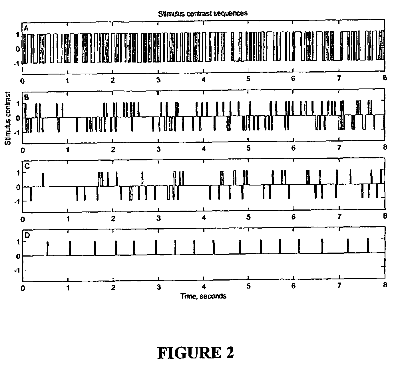
[0075]The relevant feature of the sparse nature of the pseudorandom stimulus sequences will be better understood by inspection of FIG. 2, which illustrates 4 types of pseudorandom stimulus sequences. The upper panel (A) illustrates a binary sequence where the stimulus varies between two levels. The stimulus was generated with a pseudorandom number generator with an even distribution and the probability of the stimulus being in either stimulus condition at a given time step was set to ½. Thus, the frequency of non-null stimulation was ½(50.5), equal to 25.25 pattern reversals per second per eye. The second panel (B) illustrates a ternary or bipolar version of a sparse pseudorandom stimulus sequence. Here the stimulus has three levels including a more frequent null stimulus condition, at the middle stimulus level, and two less frequent stimulus conditions, at levels above and below the null stimulus condition. In this case the probability of encountering...
example 3
Visual Stimulus
[0076]FIG. 3 illustrates a visual stimulus for a particular non-limiting embodiment in which the face of a video monitor was divided into 8 parts demarked by the bold lines. In the tests described in the figures that follow subjects observed visual stimuli presented in each of the 8 regions and evoked potentials were recorded. The numbers in each of the eight regions shown will be used in the subsequent 3 figures to refer to these regions. Black and white checkerboard patterns were presented within each region, the boundaries of the checks being shown by the thin lines. Each region had its contrast modulated in time by different pseudorandom sequences each 40 s long. For the binary sequences of FIG. 2 white checks are considered to have contrast 1 and black checks contrast −1. Thus the temporal modulation sequences caused the checks within each of the 8 regions to flip the sign of their contrast or remain the same contrast according to the state, 1 or −1, of the binar...
PUM
 Abstract
Description
Claims
Application Information
 - R&D
- Intellectual Property
- Life Sciences
- Materials
- Tech Scout
- Unparalleled Data Quality
- Higher Quality Content
- 60% Fewer Hallucinations
Browse by: Latest US Patents, China's latest patents, Technical Efficacy Thesaurus, Application Domain, Technology Topic, Popular Technical Reports.
© 2025 PatSnap. All rights reserved.Legal|Privacy policy|Modern Slavery Act Transparency Statement|Sitemap|About US| Contact US: help@patsnap.com


