Eureka AIR delivers breakthrough ideas for toughest innovation challenges, trusted by R&D personnel around the world.

Integrated closed loop system for industrial water purification

a closed loop system and industrial technology, applied in water/sludge/sewage treatment, moving filter element filters, animal husbandry, etc., to achieve the effect of reducing total surface area, optimum process efficiency, and increasing biofilm thickness

Inactive Publication Date: 2006-02-21
GREENFISH
View PDF6 Cites 137 Cited by
  • Summary
  • Abstract
  • Description
  • Claims
  • Application Information

AI Technical Summary

Benefits of technology

[0089]4. Genetically modified or genetically undesirable strains of different species of bacteria, fungi, plants, fish, shellfish or crustaceans present in the industrial system, eliminating genetic drift from the production unit to the surrounding ecosystem.
[0128]5. Repeated recirculation of waste water within the loop or bioreactor, thus increasing the purification efficiency by repeated exposure to the microorganisms in the purification reactor, is made possible by internal by-pass-systems in the loop systems or bioreactors.

Problems solved by technology

The release of nitrogen and phosphorous compounds into the environment has become one of the most pressing environmental hazards.
However, they are released in large quantities especially in industrial, domesticated farm, aquaculture or forestry agriculture areas and cause eutrophication of water recipients, first producing algal blooms and thereafter oxygen deficiency in natural waters.
Stringent requirements on the processing of biologically produced nutrients and materials are one of the limiting constraints for the establishment of new industrial, food processing, agro- and aquaculture ventures.
However, activated sludge is difficult to control (as in high intensive aquaculture systems with high rates of recirculation and water flow), due to a necessary aggregation into flocs with a subsequent floatation or sedimentation, which are all difficult to control.
It puts requirements on large sedimentation or flotation tanks, which in turn lowers the cost efficiency (U.S. Pat. No. 3,849,303, U.S. Pat. No. 5,611,927).
This means that the microorganisms are subjected to different forms of stress that will lead to loss of growth yield and efficiency of the filters or reactors, due to constraints of metabolic reversals in each cycle and interspecies competition.
Fixed bed reactors for purification as well as any reactor where most of the active biomass is attached as a biological film on an immobilized media, are subject to problems with clogging and requirement of back flushing of the filter media (U.S. Pat. No. 5,081,954).
Furthermore, the uniform distribution of nutrients, oxygen, and carbon through the filter is very difficult to control in fixed bed reactors, where a uniform distribution is actually a prerequisite for an effective process.
Numerous examples on patents disclose solutions for an even distribution of water flow in a fixed bed filter, but in practice, it is impossible to fully control the even distribution of bacteria, substrate and electron acceptors as oxygen or nitrate in the media.
More importantly, these constraints impair the means of reliable industrial control and optimisation.
However, the energy input in these systems is relatively high since they are driven by high-pressure pumps, whereby cost efficiency is lost compared to low head systems, although high pressure systems require small footprint area relative to the internal specific filtration area.
Therefore, such systems will fail in either the nitrification process or In the denitrification process if not a nearly complete degradation of organic matter precedes the nitrification and an easily biodegradable hydrocarbon is added to the denitrification process.
However, hydraulic limitations of each subprocess in the loop limit the recycle and therefore limit the maximum nitrogen removal.
In a closed loop system, where only a small part of the water is exchanged with the surrounding environment, the oxidation of organic matter before the denitrification process, like in conventional systems and patent disclosures (WO 96 / 04784), poses a reduction In the efficiency of biological water treatment, because available organic material that is desirable for the denitrification is lost in the initial oxidation process.
It is the sequence of the biological treatment processes relative to the production unit and the inflexibility of the chosen structures that are the major limitations in disclosures for water purification.
Further, the hydraulic load on the entire treatment process will be unnecessarily high.
In another embodiment in the same patent, where the sequence could be argued to be correct (first a denitrification process with a by-pass, followed by a carbon filter and nitrification) the inflexibility of not having a by-pass over the nitrification process will imply a very inefficient use of the nitrification reactor If the nitrite levels are not to become dangerously high to many aquatic organisms.
Further, the nitrification process is pursued in a 4″ gravel bed that has the obvious large footprint disadvantage when run in high intensive systems.
The greatest challenge of all in biological water purification processes is developing environments for high efficiency of the nitrification process, which is far more sensitive than denitrification and BOD-removal.
Inefficient nitrification leads to the production of nitrite, which may be a great hazard in agro- / industrial processes and especially if marine or freshwater animals are produced within the industrial system.
This main metabolic constraint is followed by the further outlined growth limitations of this organism, which is not recognized in patent WO 97 / 49279.1. One of the most limiting factors is the need for oxygen for nitrification.
Due to low residence time the nitrite oxidizing bacteria will not be able to oxidize all nitrite into nitrate.
This is especially true in systems where high flow rates of water are applied and ammonia levels exceeding 4mg / l As a result toxic nitrite is accumulated in the system.
They all result in incomplete nitrification.
But still, water flow leading to the nitrification reactor will contain high amounts of organic material that will hamper nitrification, since no BOD-oxidising reactors are positioned in-between these two processes.
Naturally, it should be considered a bad management practice to mix non-purified water with newly purified.
The three limitations with this system are:1. The sludge is always more difficult to control than biofilm processes on suspended carriers, especially in combination with aerobic anaerobic processes.2. The sludge is containing all the microorganisms, nitrifiers, denitrifiers, aerobic heterotrophs and PAOs at the same time, exposing them to cyclic changes and differential metabolic lag phases in the six purification cycles.3. The microorganisms are forced to compete for the same space, and at times, same organic material.
Thus, such a system is not efficient for the water purification itself without extensive additional water purification, unless of course the cultured plants are the main production objective and the other industrial production units are regarded as by-products (e.g. fish).
This is not easily obtained with activated sludge or high-pressure systems (U.S. Pat. No. 4,948,510).
Furthermore, high-pressure systems also require above average capital investments.

Method used


Image

  • Integrated closed loop system for industrial water purification
  • Integrated closed loop system for industrial water purification
  • Integrated closed loop system for industrial water purification

Examples


Embodiment Construction

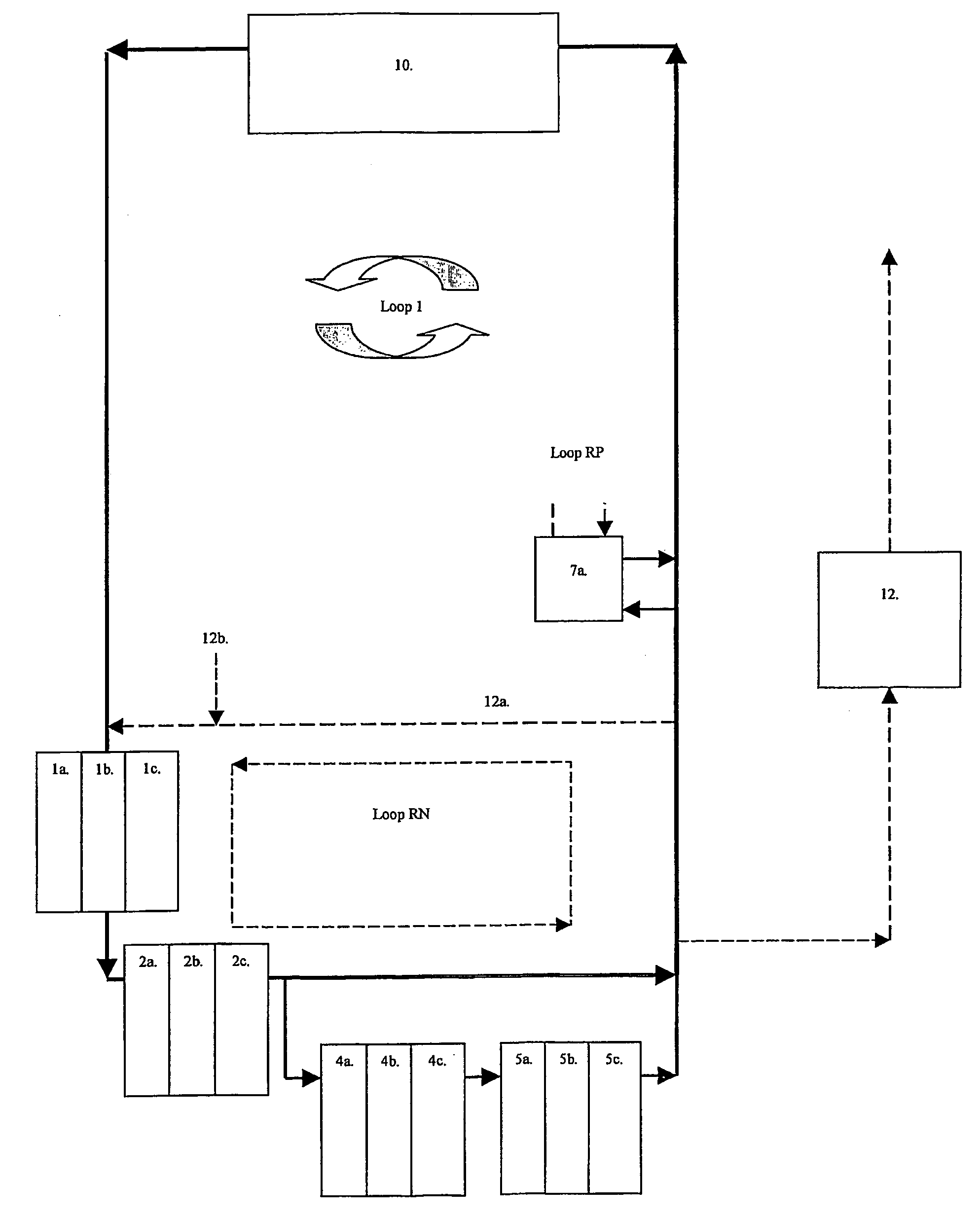
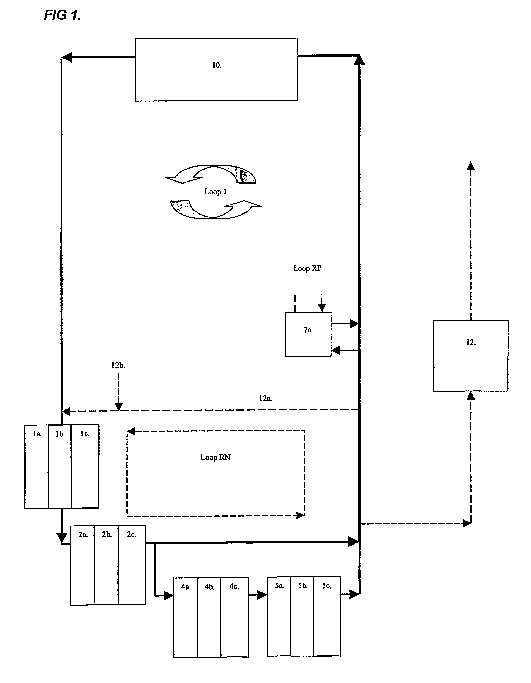
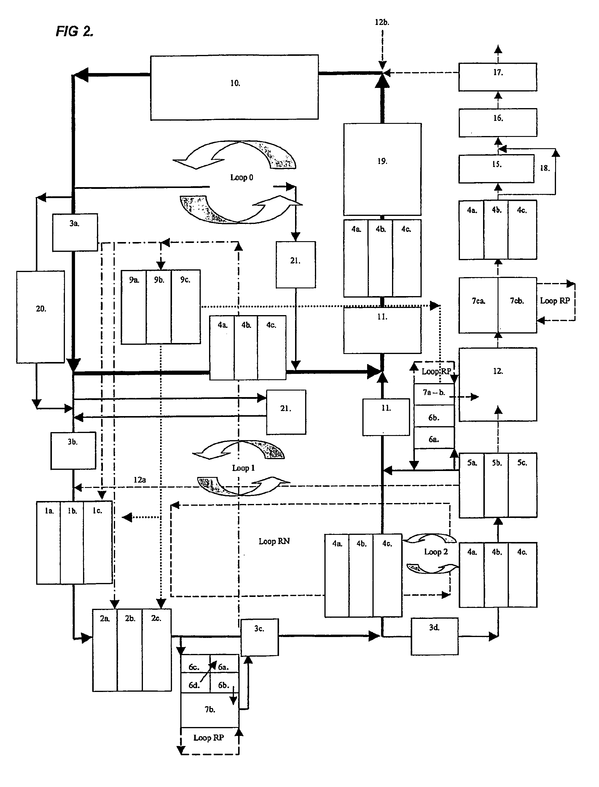
[0134]The basic aspect of the invention is the use of internally produced organic material or BOD from the production unit for the denitrification and phosphorous accumulation in a bioreactor system, preferably comprising a suspended carrier system and or activated sludge reactors, respectively. This basic aspect leads to the reduction of organic materials, which lead to the increased efficiency of nitrification. The process involves the following basic and successive purification steps:[0135]1. Oxygen reduction by internal use of BOD or by BOD addition.[0136]2. The reduction of nitrite and nitrate by denitrification to atmospheric molecular nitrogen.[0137]3. Oxidation of organic material or BOD for reduction of organic waste in the water.[0138]4. Autotrophic oxidation of ammonium-nitrogen to nitrate.[0139]5. Biological phosphorous elimination with PAO's.[0140]6. The water is recirculated back to the agro- / industrial production unit.[0141]7. Finally the oxidised nitrate-nitrogen is ...


PUM

PropertyMeasurementUnit
depthaaaaaaaaaa
wavelengthsaaaaaaaaaa

Abstract

The present invention relates to an integrated closed loop system for aquaculture in at least one culturing tank and using continuous bioreactor technology for the biological treatment and removal of organic material, nitrogen and phosphorous, comprising: an integrated, partially or wholly closed loop system for waste water treatment, where the water contains nitrogen containing compounds and / or substances, comprising at least one production unit of such nitrogen containing compounds and / or substances and using continuous bioreactor technology for the biological treatment and removal of organic matter, nitrogen and phosphorous from the said water at continuous flow, comprising: a) at least one suspended carrier bioreactor for bacterial growth under anoxic conditions to cause anaerobic denitrification, with one or several compartments, preceding b) at least one suspended-carrier bioreactor for bacterial growth under oxic conditions to cause aerobic nitrification, c) the denitrification taking place after the production unit, and d) the nitrification taking place prior to the production unit in a by-pass mode as part of the continuous flow.

Description

[0001]This application is a continuation of International Patent Application No. PCT / SEQ3 / 00198, filed Feb. 5, 2003, which claims priority to Swedish Patent Application No. 0200348-1, filed Feb. 7, 2002, both of which are incorporated herein by reference in their entirety.FIELD OF THE INVENTION[0002]The invention relates to an integrated closed loop system, or a partially closed loop system, for water purification, comprising a sequenced bioreactor system for the biological processing of nitrogen and phosphorous containing waste water from a production process.BACKGROUND OF THE INVENTION[0003]The release of nitrogen and phosphorous compounds into the environment has become one of the most pressing environmental hazards. The release is generally of no significance in low concentrations due to natural presence. However, they are released in large quantities especially in industrial, domesticated farm, aquaculture or forestry agriculture areas and cause eutrophication of water recipien...

Claims


Application Information

Patent Timeline
Patent Type & Authority Patents(United States)
IPC IPC(8): A01K63/04C02F3/30C02F1/00C02F1/32C02F1/78C02F3/06
CPCA01K63/04C02F3/302C02F3/308C02F1/001C02F1/32C02F1/78Y10S210/906Y10S210/908Y10S210/903C02F3/06Y02W10/37Y02W10/10
Inventor LINDEN, BJORNWIK, TORSTEN
Owner GREENFISH
Why Eureka
Eureka Blog
Learn More