
Production enhancement for a reactor

Inactive Publication Date: 2006-01-03
PRAXAIR TECH INC
View PDF10 Cites 56 Cited by
  • Summary
  • Abstract
  • Description
  • Claims
  • Application Information

AI Technical Summary

Benefits of technology

[0036]Although a central advantage of the present invention is that increased production may be accomplished without addition of the capital intensive add-ons discussed above, such additional equipment can be used in connection with the present invention For instance, a low temperature shift unit can be added to further increase the hydrogen production. A pre-reformer can also advantageously, albeit not without significant capital expenditure, to pre-reform the reactant and steam mixture can be pre-reformed prior to its introduction into the reaction.
is that increased production may be accomplished without addition of the capital intensive add-ons discussed above, such additional equipment can be used in connection with the present invention For instance, a low temperature shift unit can be added to further increase the hydrogen production. A pre-reformer can also advantageously, albeit not without significant capital expenditure, to pre-reform the reactant and steam mixture can be pre-reformed prior to its introduction into the reaction.

Problems solved by technology

However, it does not increase reformer throughput.
However, there is no teaching or suggestion for the use of the waste oxygen stream in the SMR combustors to enhance hydrogen production.
Because of the short residence time, the reaction section is essentially adiabatic, no significant amount of heat transfer is possible.
There is no teaching or suggestion for applying catalyst in conventional furnace based reformer systems.
However, there is no teaching or suggestion as to how this would impact existing reformers.
There are disadvantages to each of the prior art production enhancements.
Moreover, the higher flow rates and temperatures can exceed fuel system control limits, induced draft fan limits, and excess reformer tube wall temperatures.
Changes in control systems, and induced draft fans require capital and time to implement.
The main disadvantage of adding a low temperature shift unit is that it is only an option in cases where one does not already exist.
It is to be noted that adding such a unit does not actually increase the capacity of the reforming process.
These units are difficult to operate and improve operations by increasing the conversion of reformer product to hydrogen.
The low temperature shift option requires additional capital, is limited by the residual carbon dioxide content of the gas leaving the high temperature shift unit, and is of little or no value if the syngas produced by the reformer is used for producing chemicals such as methanol or ammonia.
The addition of a pre-reformer is also a capital intensive endeavor because it involves the addition of a catalytic reactor in addition to modifying the convective heat recovery section to provide the heat necessary for driving the reforming reactions.
In addition the export stream that would otherwise be produced is lost because the heat from the convective section used to drive the pre-reformer is no longer available to produce steam.
The large quantity of catalyst used in the pre-reformer is generally twice as expensive as that for the primary reformer and has a relatively short life.
Post reforming accomplished by a bypass-feed product-heat-exchange reformer is also capital intensive because it involves the addition of a catalytic reactor downstream of the primary reformer.
Maintenance is difficult on this heat-exchanger reactor.
In addition, export steam production is lost because the heat in the exhaust of the primary reformer is used to drive additional hydrocarbon conversion to carbon monoxide and hydrogen.
In addition, significant changes to the carbon dioxide removal system may be required because of the higher levels of carbon dioxide produced to raise the inlet temperature to the reformer.

Method used


Image

  • Production enhancement for a reactor
  • Production enhancement for a reactor
  • Production enhancement for a reactor

Examples


Embodiment Construction

[0046]It is to be noted that the present invention will be described in relation to a steam methane reformer. This description should not, however, be taken as being limiting in that, as mentioned above, the present invention has application to any reactor having combustion sections used to generate heat to support endothermic chemical reactions taking place within an endothermic reaction sections. Specifically, the present invention could also be used in connection with pyrolysis furnaces and dehydrogenation furnaces.

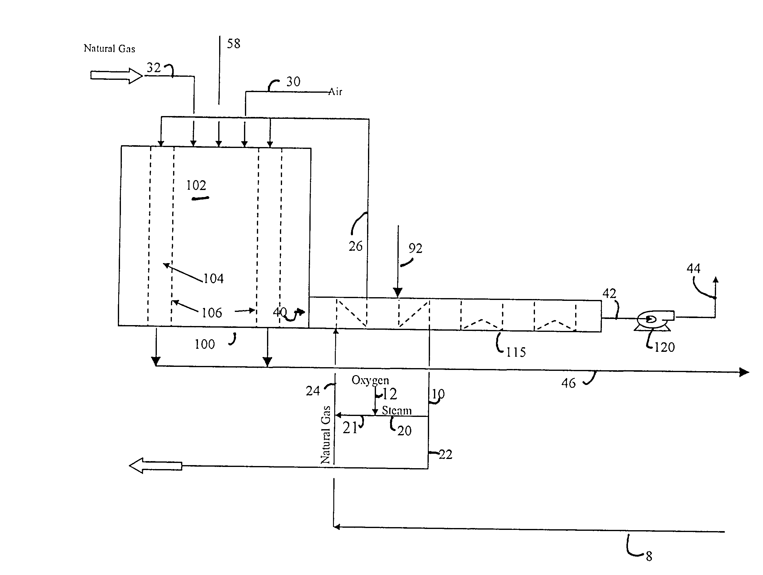
[0047]In accordance with the present invention, supplemental oxygen is added either directly to the combustion section, the reaction section or a mixture of a reactant and steam or steam alone that is fed to the reactant section. The amount of oxygen added are selected in a known manner to prevent a temperature rise within the reformer that is greater than about 200° C.

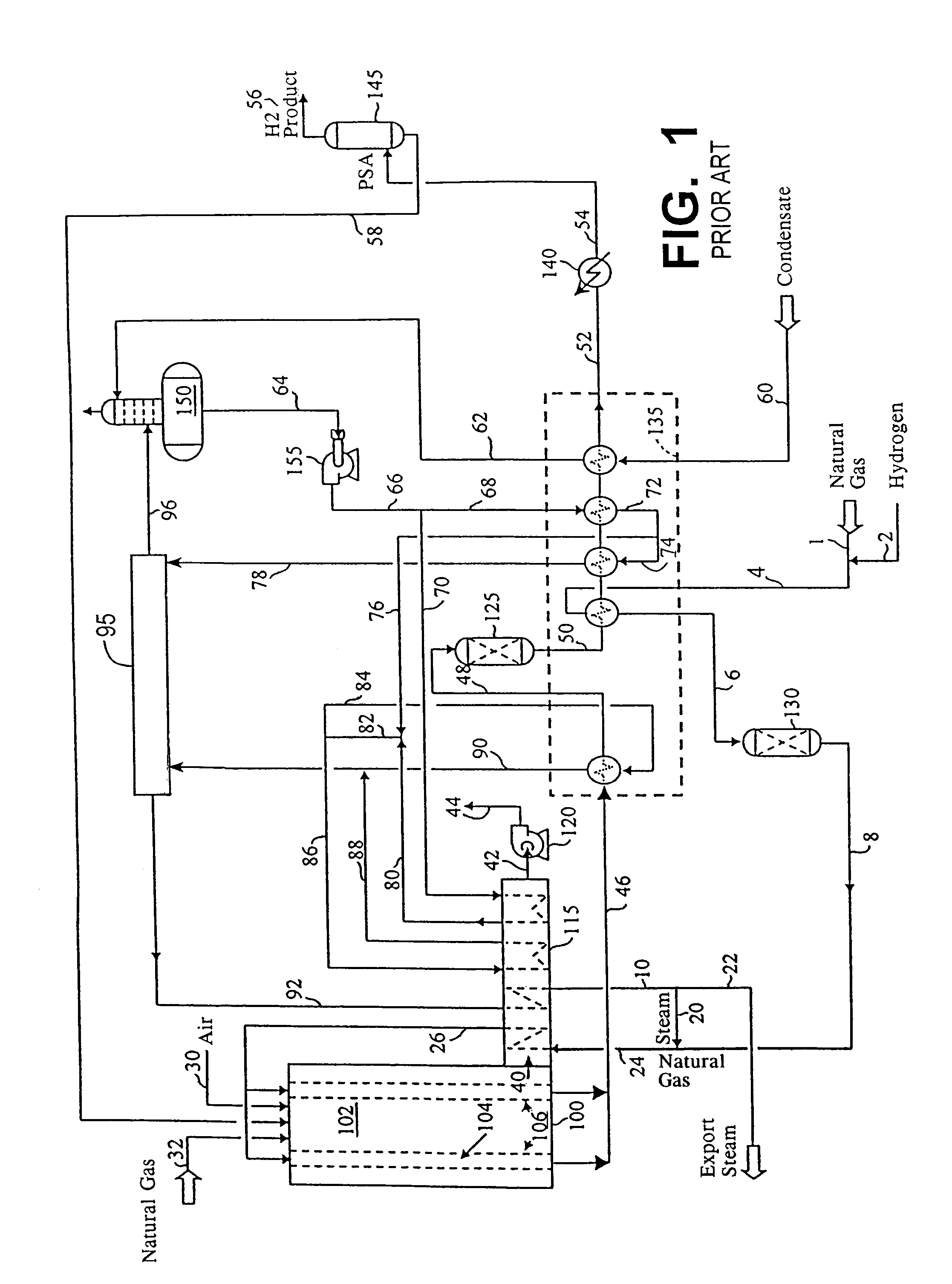
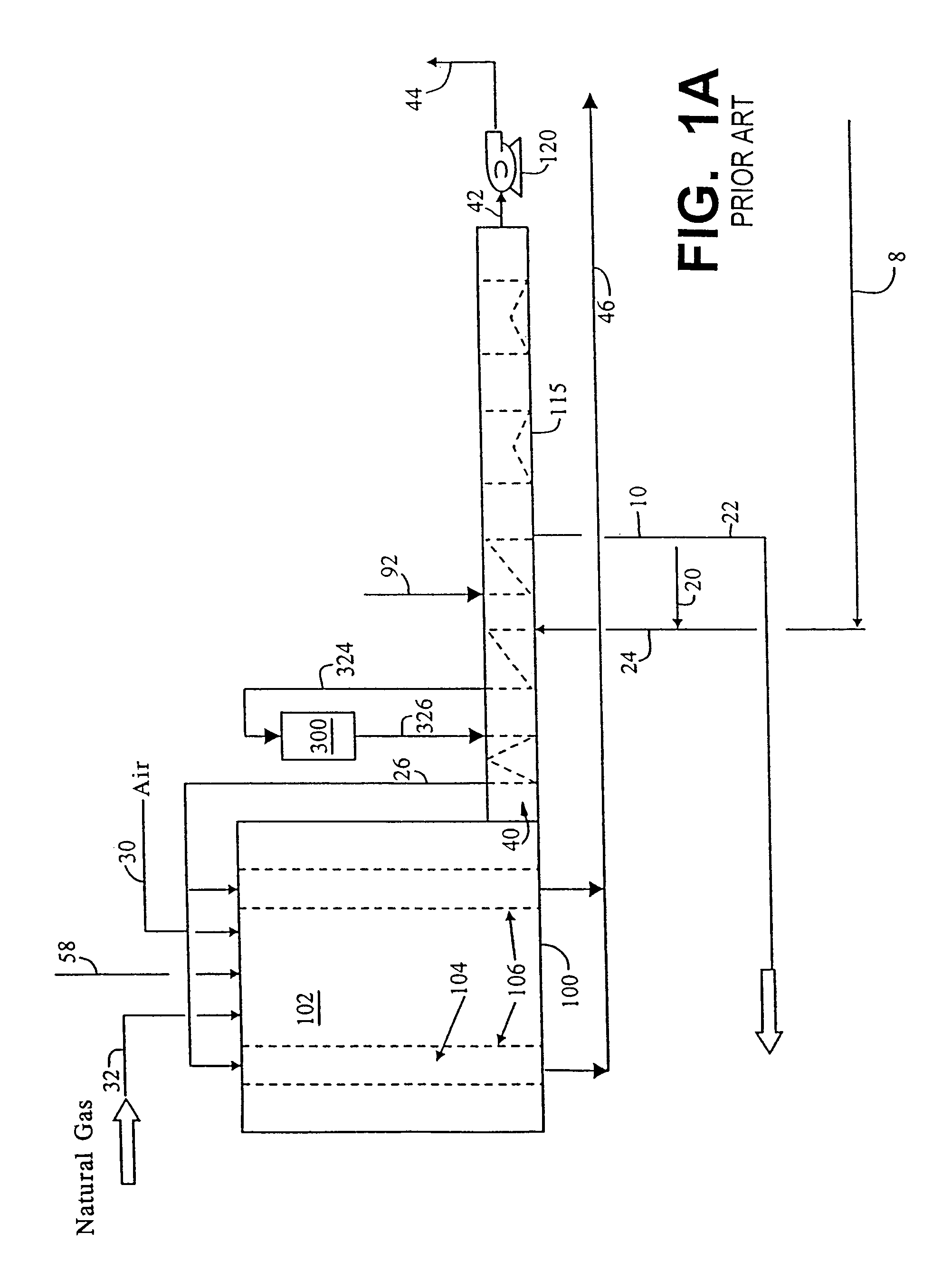
[0048]FIG. 1 shows the schematic diagram representative of a steam methane reformer system used for t...


PUM


Abstract

This invention is directed to a process for increasing production of product that is formed in a reactor having a combustion section in which fuel is burned to produce heat to drive an endothermic reaction occurring within a reaction section. Production is increased by adding supplemental oxygen to air or other oxygen containing gas used to support combustion in the combustion section, thereby to generate more heat to support an increase in the endothermic reaction. Additionally, supplemental oxygen can be introduced into the reaction section to partially oxidize a reactant to generate heat and to allow an increase in the production of the product. Supplemental oxygen may be added directly to the steam-methane mixture, or to the combustion air.

Description

RELATED APPLICATIONS[0001]This is a continuation-in-part of application Ser. No. 10 / 024,056 filed Dec. 17, 2001, now abandoned.FIELD OF THE INVENTION[0002]The present invention relates to a process for enhancing the production of a product within a reactor in which the product is produced by an endothermic reaction between a reactant and steam and heat is generated to support the endothermic reaction by either oxidation or partial oxidation of a fuel. More particularly, the present invention relates to such a process in which production is enhanced by introduction of supplemental oxygen into the reactor. Still, more particularly, the present invention relates to such a process in which the reactor is a steam methane reformer, a pyrolysis furnace or a dehydrogenation furnace.BACKGROUND OF THE INVENTION[0003]The production of products by various endothermic reactions involving steam takes place in a variety of reactors. For instance, synthesis gases (“syngas”) containing hydrogen and ...

Claims


Application Information

Patent Timeline
IPC IPC(8): C01B3/32C01B3/38
CPCC01B3/382C01B3/384C01B2203/0233C01B2203/0261C01B2203/0283C01B2203/043C01B2203/1695C01B2203/0816C01B2203/0822C01B2203/0827C01B2203/127C01B2203/1623C01B2203/0811Y02P20/10C01B3/24C01B3/32
Inventor DRNEVICH, RAYMOND FRANCISFENNER, GARY WAYNEKOBAYASHI, HISASHIBOOL, III, LAWRENCE E.
Owner PRAXAIR TECH INC
Learn More