3D stereo real-time sensor system, method and computer program therefor

Inactive Publication Date: 2005-12-27
3D IMAGE PROZESSING
View PDF9 Cites 25 Cited by
  • Summary
  • Abstract
  • Description
  • Claims
  • Application Information

AI Technical Summary

Benefits of technology

[0031]Consequently, it is the purpose of the present invention to specify an image processing device that can process stereoscopic images in real time and which can be implemented with simple means and low expense. Furthermore, it is the purpose of the present invention to specify a coherence detector that can be used with the stated device.
[0035]Due to this invented design, the supplied image signals can be processed at the speed that they are supplied by image receivers. Thus the image data processing is possible to attain depth information with little expense and in real time.
[0036]This high processing speed (real time) of the system is an important advantage over the state of the art. At an image rate of 25 images per second, for example, which are sent to the image receiver system and are processed by it in real time, the system or the method implemented with it is superior to the configuration or method known from the state of the art by a speed factor of 100.
[0038]Due to the potential to evaluate a measured object without the ancillary marking, the requirement for a projection unit is also eliminated. Consequently, the invented device is more compact and light, and its handling is simplified and more versatile potentials will result.
[0039]In addition, a pretreatment of the measured object itself, for example, coverage of the measured object with bright powder to eliminate reflectivity and shine on the object surface before the measurement and removal of the powder after completion of the measurement, can be eliminated in the invented device. Due to the savings in these work steps, the invented device operates faster and at less cost.

Problems solved by technology

However, this system is not suitable for real-time applications.
However, a disadvantage of this method is that under certain circumstances, one image will have to be evaluated for each projected line, which is exceptionally time-consuming, so that a system of this kind is not useful for real-time applications.
In addition, it is particularly troublesome that the particular measured object has to be illuminated.
Of course, under laboratory conditions this does not pose a problem, but in practice it is nearly impossible when measurements are to be taken in situations as in road traffic or under the impeded, real situations prevailing with telescopes or microscopes.
Although this method operates in real time, it is associated with the restrictive requirement that the object and the background must be white, so that the method cannot be used everywhere.
However, transit time methods require a complicated signal processing, and in addition, are dependent on the properties of the surrounding medium, which affects the propagation properties of the particular measured signal.
In addition, contrast depth methods are used, but they can only be applied when the object size and the opening of an objective lens are in a certain ratio to each other, such as in microscopy.
Due to repeated shifting of the focal plane and subsequent evaluation, an elevation line map of the object can be produced, but it is complicated.
However, if we try to shift these methods into special computer systems, the development and hardware expense will very quickly exceed the financially feasible limits.
The market introduction of such systems has failed heretofore, either due to too low a processing speed, or due to too high a system price.
They are also fast, since images only have to be processed at those sites where the properties are encountered.
This leads to a notable reduction in data.
However, disparities can only be computed at those locations where the selected properties were found.
At all other locations of the image, it is necessary to use an interpolation, which then necessitates additional, time-consuming calculation steps.
The more dense the properties, the more difficult will it be to assign them to each other.
The final allocation can only be made on the basis of complicated methods which leads to a reduced processing speed.
Therefore, very stable algorithms have to be used to allocate the mutually corresponding brightnesses, and this requires significant computing time.
However, the raw disparity maps typically contain only displacements in the range of accuracy of one image element (pixel), so that the resolution is limited.
Typically these methods also calculate disparities accurate only to one picture element, but this is not accurate enough for numerous applications.
In summary, we find that intensity-based methods do indeed provide a dense disparity map (one disparity value for nearly every image point), but minimizing of the error as in the method to minimize the difference, is time-consuming and therefore it is not suitable for real time applications.
The reduction in the needed computation time can be achieved by the use of hierarchical methods, but it is only possible by the use of complicated algorithmic structures that cannot run in parallel and whose hardware implementation is exceptionally complicated and thus cost-intensive.
Furthermore, phase-based stereo methods are the subject to current investigations.
This complicates the used algorithms and makes a hardware implementation complicated and cost-intensive.

Method used


Image

  • 3D stereo real-time sensor system, method and computer program therefor
  • 3D stereo real-time sensor system, method and computer program therefor
  • 3D stereo real-time sensor system, method and computer program therefor

Examples


Embodiment Construction

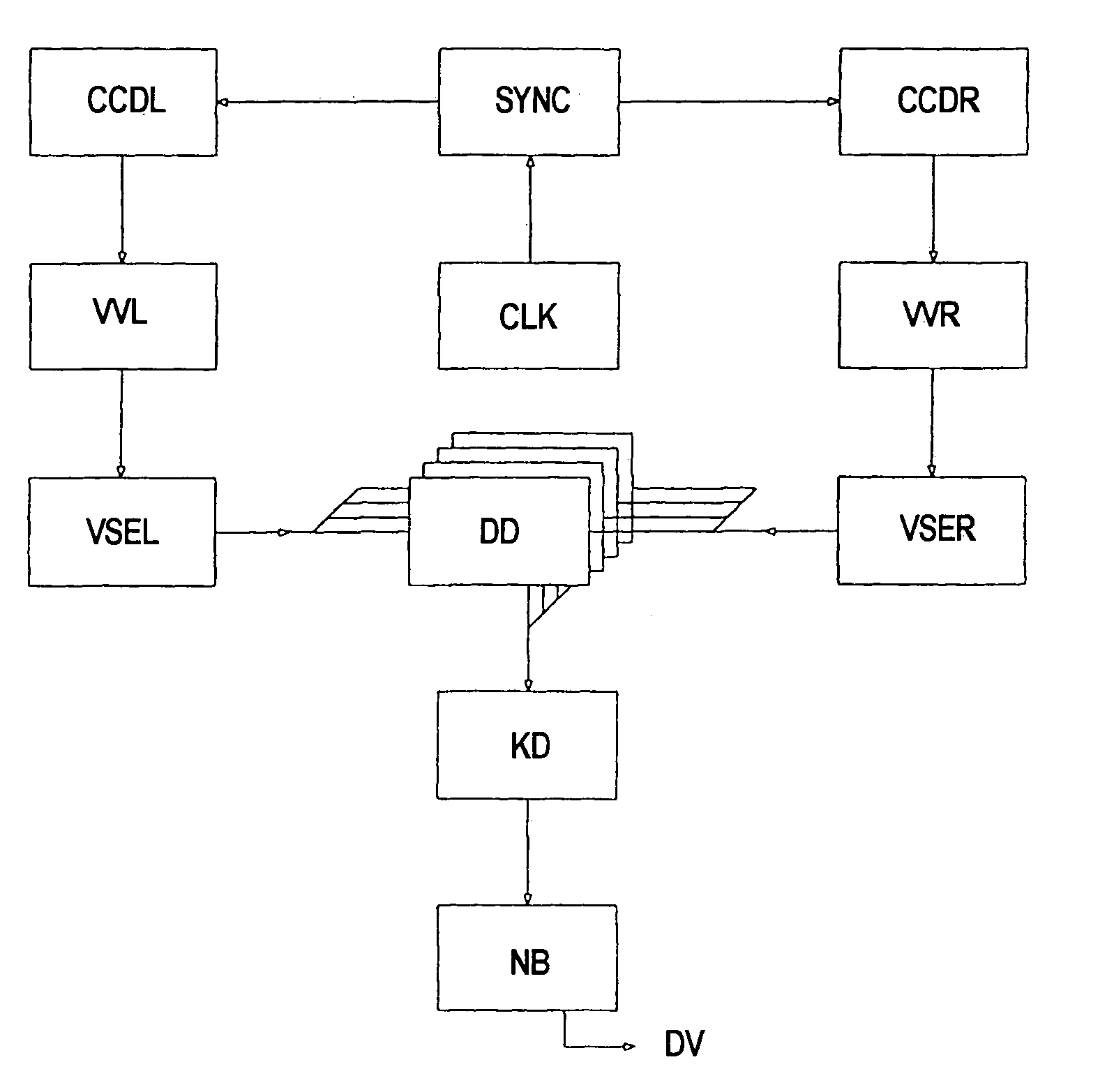
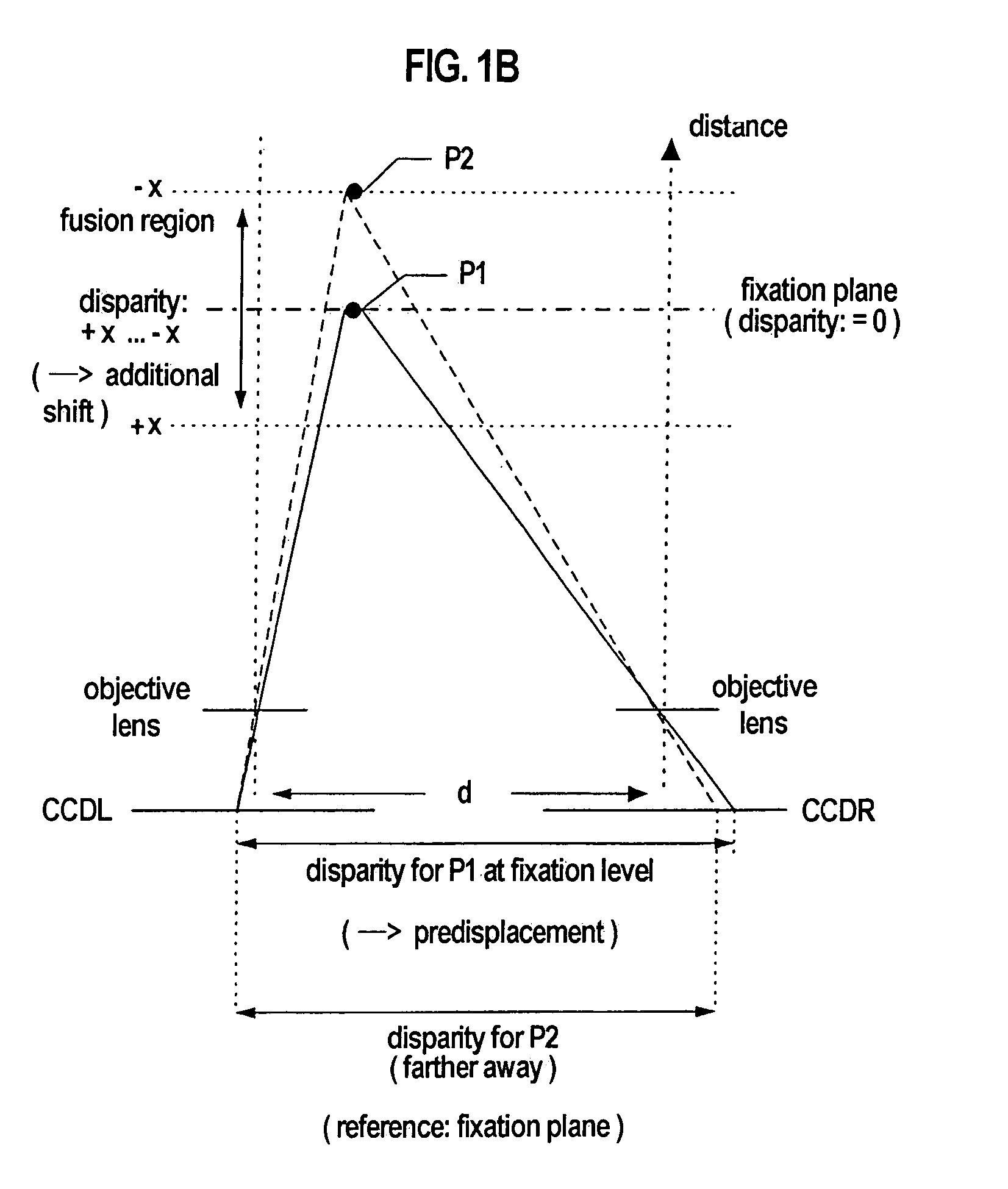
[0058]The following detailed description illustrates the invention by way of example, not by way of limitation of the principles of the invention. This description will clearly enable one skilled in the art to make and use the invention, and describes several embodiments, adaptations, variations, alternatives and uses of the invention, including what is presently believe to be the best mode of carrying out the invention.

[0059]In this regard, the invention is illustrated in the several figures, and is of sufficient complexity that the many parts, interrelationships, and sub-combinations thereof simply cannot be fully illustrated in a single patent-type drawing. For clarity and conciseness, several of the drawings show in schematic, or omit, parts that are not essential in that drawing to a description of a particular feature, aspect or principle of the invention being disclosed. Thus, the best mode embodiment of one feature may be shown in one drawing, and the best mode of another fe...


PUM


Abstract

The invention pertains to an image processing device, in particular a device for stereoscopic image processing, and to a coherence detector used thereon. The image processing device can process stereoscopic images in real time and can be implemented with simple means and low expense. Two alternative embodiments of the coherence detector are disclosed. The image signals can be processed at the speed that they are supplied by image receivers, and thus image data processing is possible to attain depth information with little expense and in real time.

Description

CROSS REFERENCE TO RELATED CASES[0001]This Application is a based on German Patent Application P 197 52 047.2, filed 24 Nov. 1997, and on German Patent Application P 198 51 993.1, filed 11 Nov. 1998, each by the same Inventors. Applicants hereby claim the priority of each of these earlier filed foreign applications pursuant to 35 U.S.C. §119(a).DESCRIPTION[0002]1. Technical Field[0003]The present invention pertains to an image processing device, and in particular a device for stereoscopic image processing, a coherence detector used thereon, and methods and computer programs therefor.[0004]2. Background of the Invention[0005]The optical determination of the three-dimensional environment has become increasingly important for some time. In particular in automated manufacturing processes and on the robots used therein, in addition to two-dimensional coordinates, depth information must also be available with regard to an object (to be processed), in order to control the robot appropriate...

Claims


Application Information

Patent Timeline
IPC IPC(8): G01C11/06G01B11/00G01B11/24G01B11/245G06T1/00G06T7/00H04N13/239
CPCG06T7/0075G06T2200/28G06T2207/10012H04N13/0239H04N2013/0081G06T7/593H04N13/239
Inventor WEIGLHOFER, GERHARDPAUKER, FRITZHENKEL, ROLF
Owner 3D IMAGE PROZESSING
Why Eureka
Try Eureka