
Electro-hydrostatic actuator

a technology of electrohydrostatic actuators and actuators, which is applied in the direction of positive displacement liquid engines, piston pumps, fluid couplings, etc., can solve the problems of signal transmission loss and other related difficulties, system maintenance costs, and rather bulky structure of actuators, so as to reduce transmission loss

Inactive Publication Date: 2005-12-13
YOUNG & FRANKLIN
View PDF19 Cites 32 Cited by
  • Summary
  • Abstract
  • Description
  • Claims
  • Application Information

AI Technical Summary

Benefits of technology

[0010]Another object of the present invention is to provide a more compact, non-hazardous valve actuator.
[0011]Yet another object of the present invention is to reduce transmission loss typical of an electro-hydrostatic valve actuator.

Problems solved by technology

In order to gain certification, many of the actuators are housed in rather bulky complex structures, external power supply and controls that are costly to construct and difficult to service and maintain in the field.
The cabling between the actuator and the controller can be relatively long which can lead to signal transmission loses and other related difficulties.
Although the Gerbe device provides for improved motor cooling, the electronic controls for the motor are situated at a location remote from the tank housing and is therefore subject to all the problems associated with transmission lines of any appreciable length.
Furthermore, because the electrical unit associated with the actuator must be housed in its own non-hazardous container, the system is costly to maintain.

Method used


Image

  • Electro-hydrostatic actuator
  • Electro-hydrostatic actuator
  • Electro-hydrostatic actuator

Examples


Embodiment Construction

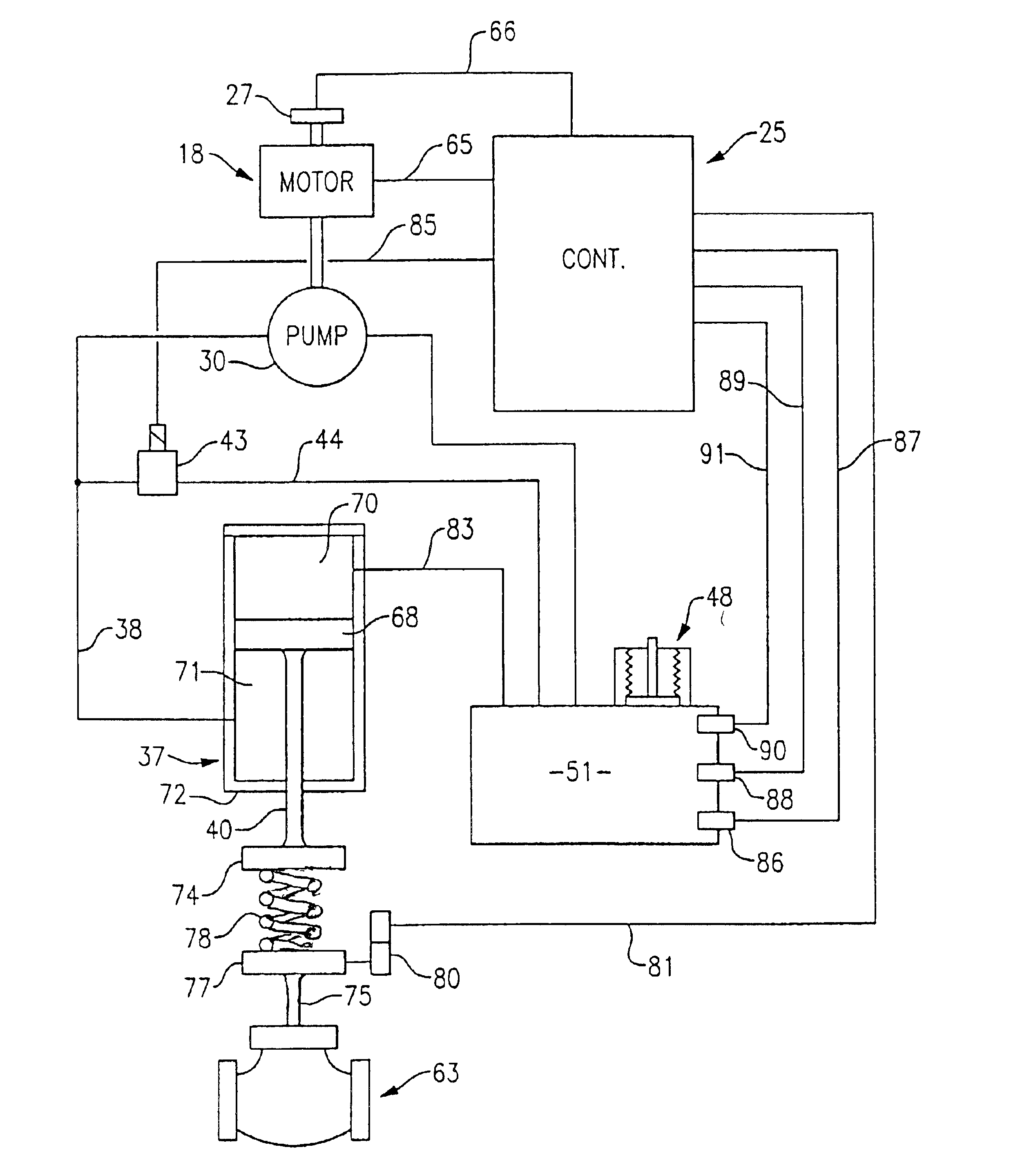
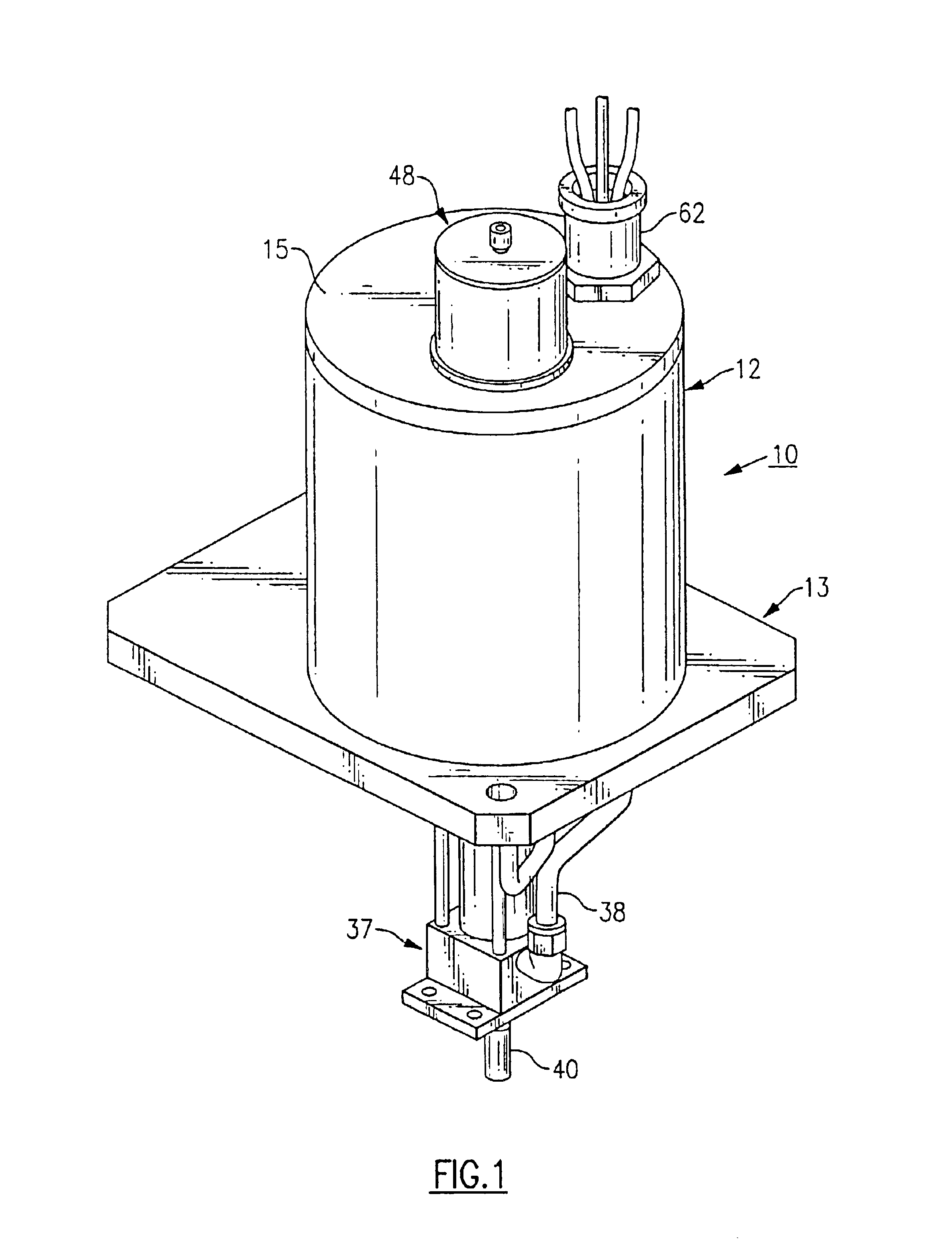
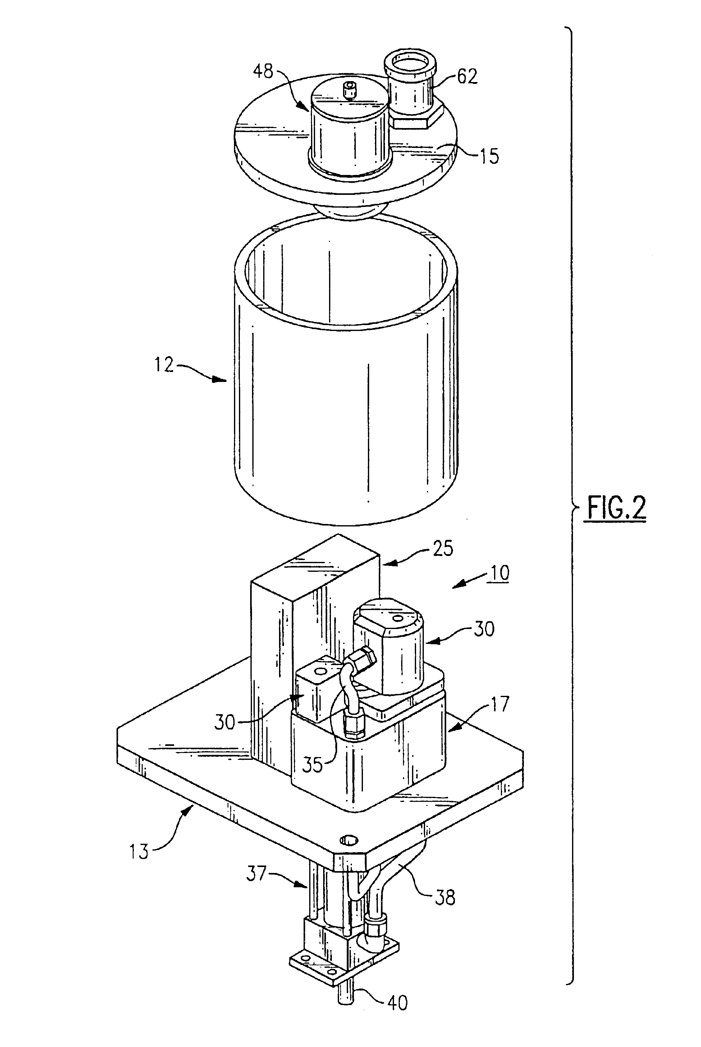
[0022]Turning initially to FIGS. 1-3 there is illustrated a linear electro-hydrostatic actuator, generally referenced 10, that embodies the teachings of the present invention. Although, the actuator is ideally suited to control the positioning of a flow control valve, it should be evident from the disclosure below that the actuator is equally adaptable to control the positioning of a wide variety of devices. The actuator includes a cylindrical housing 12 that is seated upon a base plate 13. The top of the housing is closed by a top cover 15. Although not shown, the housing is provided with suitable seals preventing fluid from escaping from the housing.

[0023]As illustrated in FIGS. 2 and 3, a support block 17 is mounted upon the base which houses a brushless d.c. motor 18 within a motor compartment 19. The motor includes a permanent magnet 20 that is mounted upon the rotor section 21 of the motor and windings 22 located upon the motor stator 23. The motor is designed to yield high en...


PUM


Abstract

An electro-hydrostatic actuator having a sealed housing filled with a dielectric fluid. A motor driven pump and electronics for controlling the pump are all immersed in the fluid. The pump is arranged to deliver fluid from the housing to a hydraulic cylinder to control the positioning of the piston rod. A solenoid operated valve is integrated as a bypass or tip valve for quick fail safe position. The actuator is ideally suited to control various types of plunger valves. In one embodiment of the invention, the hydraulic cylinder is located outside of the housing and in another embodiment the cylinder is located inside of the housing.

Description

BACKGROUND OF THE INVENTION[0001]The invention relates to an electro-hydrostatic actuator that is ideally suited to control the positioning of a valve or any other similar device.[0002]More specifically, this invention relates to a compact electrically operated linear actuator integrates all controls and components so rapidly and efficiently heat dissipation and cooling to component parts is provided.[0003]Current demands on power generation systems and valve controls require that the actuators be electrically controlled and include fail safe features. In many countries, linear actuator of the type herein disclosed also require certification when employed in an environment where an explosion might take place as for example in controlling valves utilized in gas or oil pipelines or in certain processing plants where volatile chemicals are used in the process. In order to gain certification, many of the actuators are housed in rather bulky complex structures, external power supply and ...

Claims


Application Information

Patent Timeline
IPC IPC(8): F01C21/10F04C2/18F04C11/00F16K31/00F16K31/56
CPCF01C21/10F04C2/18F04C11/008F16K31/003F16K31/56
Inventor SILVA, GABRIEL
Owner YOUNG & FRANKLIN
Learn More