State save-on-power-down using GMR non-volatile elements

Active Publication Date: 2005-12-06
MICRON TECH INC
View PDF3 Cites 6 Cited by
  • Summary
  • Abstract
  • Description
  • Claims
  • Application Information

AI Technical Summary

Benefits of technology

[0010]The present invention provides a method and device that senses a power down sequence and provides a write current for storing a digital logic state retained in a volatile memory device to a non-volatile GMR memory device. In one embodiment, aforementioned needs may be satisfied by a memory device having a data line and a GMR storage circuit, wherein the memory device comprises at least one GMR storage cell that is coupled to the data line wherein the GMR storage cell magnetically stores

Problems solved by technology

Unfortunately, SRAM and DRAM require a continuous supply of power to maintain a particular defined logic state, and DRAM capacitors further require a periodic charge refresh from the inline access transistor to maintain the particular defined logic-state.
Therefore, conventional semiconductor random access memory (RAM) is considered volatile memory due to the fact that data may be lost with the loss or interruption of power.
Implementing this approach may be cumbersome and inconvenient in that additional devices and circuitry, including the auxiliary power source and power switching circuitry, may be required.
Therefore, if the primary power source fails for an extended period of time, the auxiliary power source may also eventually fail causing the conventional memory devices to lose the logic states or data stored therein due to the extended period of time of the power failure.
Although GMR devices may facilitate the adverse effects of losing data during power interrupts, GMR devices typically require a current pulse sufficiently capable of generating orthogonal magnetic fields, which may be difficult to implement during loss of power.
Auxiliary power sources may be used to provide enough power for storing logic states in GMR devices, but the additional cost associated with using auxiliary power components may deter the use thereof.

Method used


Image

  • State save-on-power-down using GMR non-volatile elements
  • State save-on-power-down using GMR non-volatile elements
  • State save-on-power-down using GMR non-volatile elements

Examples


Embodiment Construction

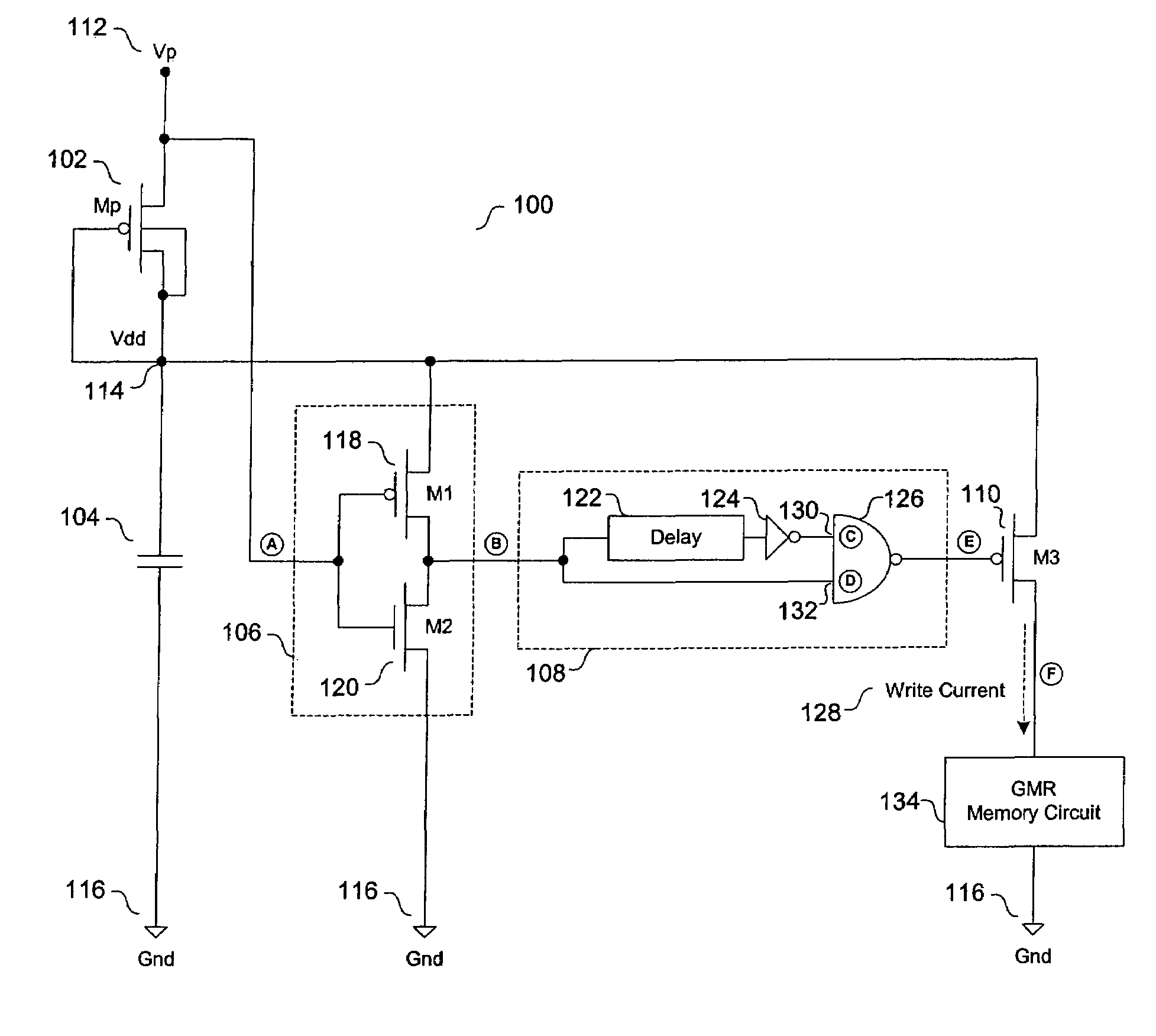
[0023]Reference will now be made to the drawings wherein like numerals refer to like parts throughout. FIG. 1A illustrates one embodiment of a save-on-power-down circuit 100. The save-on-power-down circuit 100 comprises an isolation transistor (Mp) 102, a charge storage device (C) 104, an inverter circuit 106, a positive-edge-triggered pulse generating circuit 108, and a load transistor (M3) 110. The isolation transistor 102, in this implementation, may comprise a p-channel metal-oxide semiconductor field effect transistor (MOSFET), wherein the substrate terminal is connected to the source terminal. Additionally, the drain terminal of the isolation transistor 102 may be connected to a supply voltage (Vp) 112, and the gate terminal and the source terminal of the isolation transistor 102 are connected to the node 114, which may be preferably raised to the potential of an operating voltage (Vdd). In one aspect, the charge storage device 104 may be preferably a capacitor with a capacita...


PUM


Abstract

The semiconductor industry seeks to reduce the risk of traditional volatile storage devices with improved non-volatile storage devices. The increased demand for a significantly advanced, efficient, and non-volatile data retention technique has driven the development of integrated giant-magneto-resistive (GMR) structures. A non-volatile logic state retention devices, such as GMR storage elements, and concerns a save-on-power-down circuit that may be integrated with conventional semiconductor-based computing, logic, and memory devices to retain volatile logic states and / or volatile digital information in a non-volatile manner.

Description

[0001]This invention was made with Government support under Contract Number N00030-99-C-0019 awarded by Charles Stark Draper Laboratory. The Government has certain rights in this invention.BACKGROUND OF THE INVENTION[0002]1. Field of the Invention[0003]The present invention relates to volatile memory and, in particular, refers to a method and device for providing a write current for storing a digital logic state in a giant magneto-resistance (GMR) element during a power down event.[0004]2. Description of the Related Art[0005]Since the introduction of the digital computer, electronic storage devices have been a vital resource for the retention of binary data. Conventional electronic storage devices, such as static random access memory (SRAM) and dynamic random access memory (DRAM), have been successfully integrated into computing devices for storing digital information. SRAM storage devices utilize static latch structures as storage cells. Typically, an SRAM latch structure is a comp...

Claims


Application Information

Patent Timeline
IPC IPC(8): G11C5/14G11C11/00G11C11/16
CPCG11C5/14G11C5/144G11C11/16
Inventor LU, YONGKATTI, ROMNEY R.
Owner MICRON TECH INC
Why Eureka
Try Eureka