
Power transmission device

a transmission device and power technology, applied in the direction of ac-ac conversion, dc-dc conversion, dc-dc conversion, etc., can solve problems such as unstable circuit operation, and achieve the effect of stable circuit operation

Active Publication Date: 2018-07-24
NTN CORP
View PDF20 Cites 1 Cited by
  • Summary
  • Abstract
  • Description
  • Claims
  • Application Information

AI Technical Summary

Benefits of technology

The present invention provides a power transmission device that is less affected by switching noise, making the circuit operation more stable. This is achieved by generating a delayed signal and a switch open / close signal through a comparison between the delayed signal and an AC power supply voltage signal, reducing the impact of switching noise. The device also includes a delayed signal delaying unit that delays the rising and falling of the delayed signal based on the magnitude of the AC power supply voltage signal, ensuring a sufficient pulse width for the switch open / close signal and a less distorted current waveform, improving the power factor of the device. The AC power supply voltage signal is generated using a second isolation transformer to isolate the primary and secondary coils from each other, preventing noise from affecting the secondary side and enhancing safety.

Problems solved by technology

Then, in the case of performing the PWM control using the current signal, there is a possibility that the circuit operation becomes unstable due to switching noise from the switching element 52.

Method used


Image

  • Power transmission device
  • Power transmission device
  • Power transmission device

Examples


Embodiment Construction

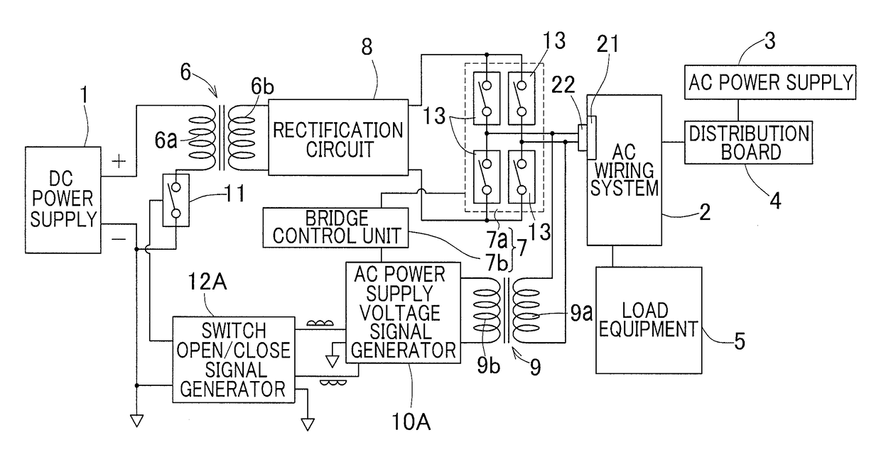
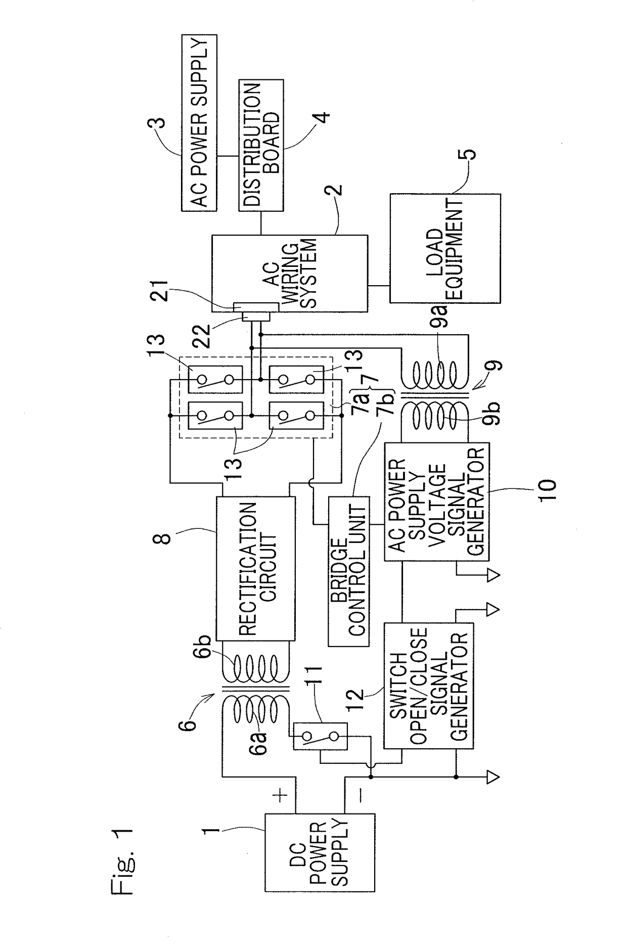
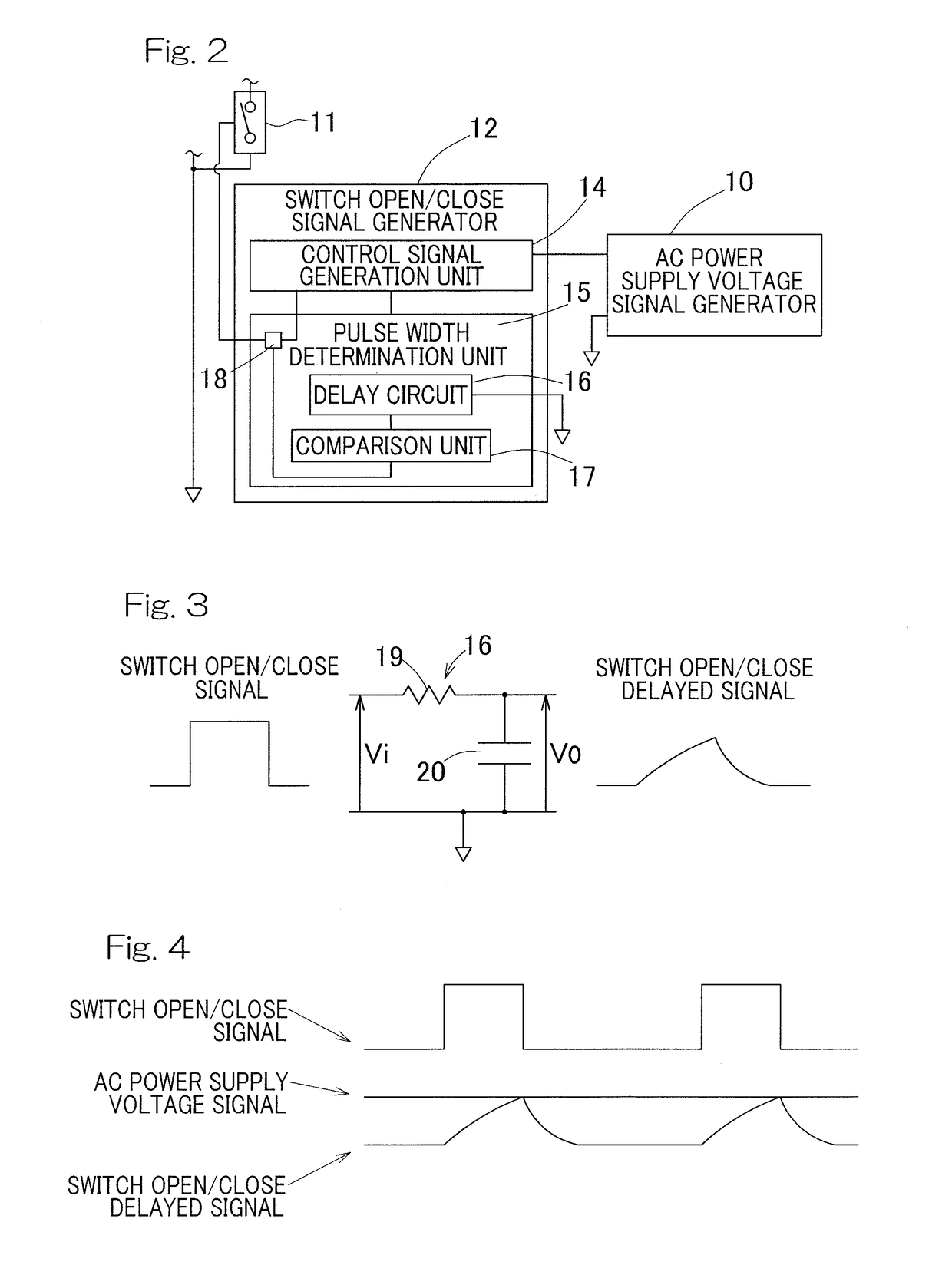
[0059]A power transmission device according to the first embodiment of the present invention will be described with reference to FIGS. 1 to 4. FIG. 1 is a circuit diagram of the power transmission device according to the present embodiment. The power transmission device transmits power from a DC power supply 1 to an AC wiring system 2 which is an indoor wiring. The power transmission device is, for example, capable of supplying power generated by the DC power supply 1 such as a photovoltaic power generation device to the AC wiring system 2 in a house or the like, connected to an AC commercial power supply, so as to allow the power to be consumed in the house or the like.

[0060]The power transmission device is connected between the AC wiring system 2 connected to the AC power supply 3, and the DC power supply 1. The AC wiring system 2 is connected to the single-phase AC power supply 3 via a distribution board 4 of the house or the like, for example. Voltage on the wiring on the indoor...


PUM


Abstract

This power transmission device is connected between an AC wiring system connected to an AC power supply, and a DC power supply, and transmits power from the DC power supply to the AC wiring system. The power transmission device includes an AC power supply voltage signal generator, a power converter, a DC voltage conversion unit, a switching element, and a switch open / close signal generator. The switch open / close signal generator includes: a control signal generation unit to generate a control signal formed from a pulse signal; and a pulse width determination unit to receive the control signal and generate a delayed signal obtained by delaying rising of the control signal, and when the delayed signal becomes a value corresponding to a magnitude of voltage of the AC power supply voltage signal, cause the control signal to fall, thereby making the control signal into the switch open / close signal.

Description

CROSS REFERENCE TO THE RELATED APPLICATION[0001]This application is a continuation application, under 35 U.S.C. § 111(a), of international application No. PCT / JP2015 / 070739, filed Jul. 21, 2015, which is based on and claims Convention priority to Japanese patent application No. 2014-150742, filed Jul. 24, 2014 and Japanese patent application No. 2014-151622, filed Jul. 25, 2014, the entire disclosures of which are herein incorporated by reference as a part of this application.BACKGROUND OF THE INVENTION[0002]Field of the Invention[0003]The present invention relates to a power (electric power) transmission device capable of supplying power generated by a DC power supply such as a photovoltaic power generation device to a commercial power supply for a dwelling house or the like so as to allow the power to be consumed in the house or the like, for example.[0004]Description of Related Art[0005]Conventionally, there has been proposed a device that transmits a power from a DC power supply...

Claims


Application Information

Patent Timeline
Patent Type & Authority Patents(United States)
IPC IPC(8): H02M5/458H02J3/38
CPCH02J3/383H02M5/458Y02E10/56H02M3/33507H02M1/007H02M7/53871H02M1/12H02M1/4208H02M7/5395H02J2300/24H02J2310/12H02J3/381H02J3/38H02M3/28H02M7/48
Inventor MIZUTANI, MASATOSHINODA, HIROYUKIMORI, NATSUHIKOKAWAI, TOMOYA
Owner NTN CORP
Learn More