High-frequency delay-locked loop and clock processing method for same

a delay-locked loop and high-frequency technology, applied in the field of delay-locked loops, can solve the problems of inability to obtain predetermined output clocks and disappearing high-level levels

Active Publication Date: 2017-12-21
XI AN UNIIC SEMICON CO LTD
View PDF3 Cites 1 Cited by
  • Summary
  • Abstract
  • Description
  • Claims
  • Application Information

AI Technical Summary

Benefits of technology

The present invention solves the problem of signal stability in high-frequency delay-locked loops. By adjusting the pulse width of the input clock and generating the fixed pulse width with the input clock's own pulses, the input clock is ensured to have enough pulse width during transmission without compromising signal quality. This guarantees the stability and reliability of signal transmission while improving transmission quality. The invention is simple in circuit structure and can be widely used.

Problems solved by technology

That is, after the clock with a high level of 300 ps is delayed, the high level will disappear and a predetermined output clock cannot be obtained.

Method used


Image

  • High-frequency delay-locked loop and clock processing method for same
  • High-frequency delay-locked loop and clock processing method for same
  • High-frequency delay-locked loop and clock processing method for same

Examples


Embodiment Construction

[0026]The present invention will further be described in details with reference to specific examples, and it is to be understood that the following description is intended to be illustrative of the invention and not to limit the invention.

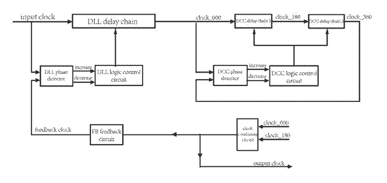
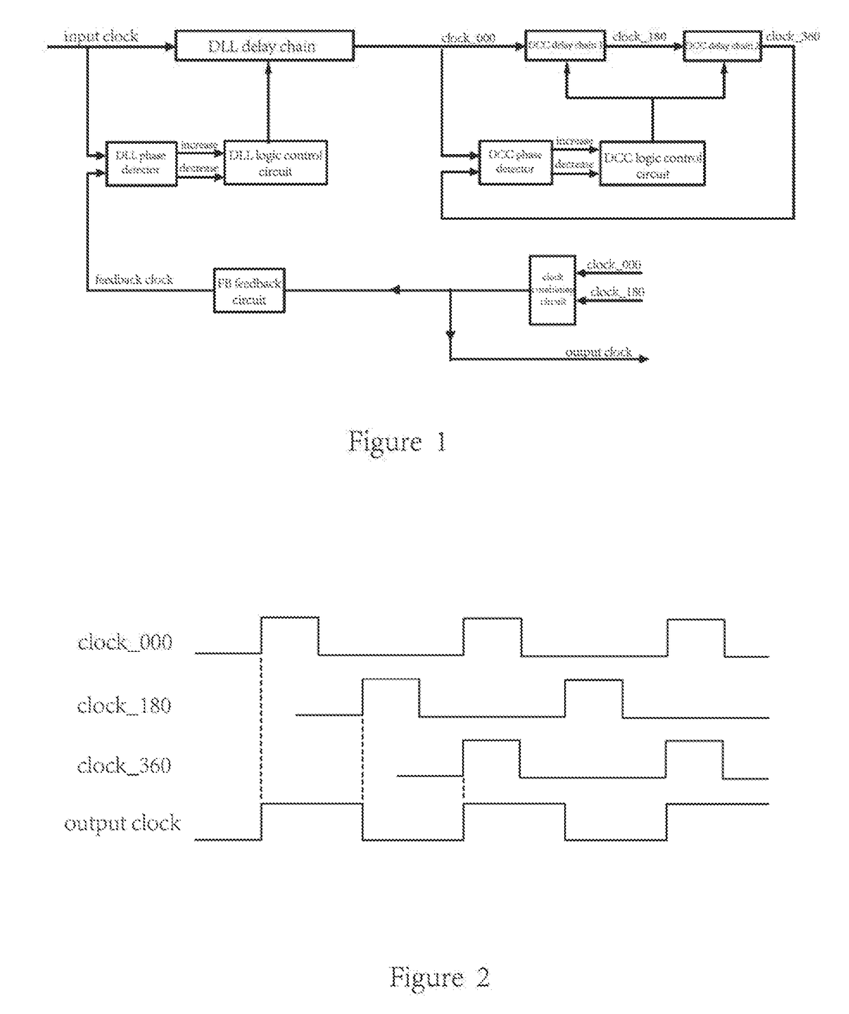
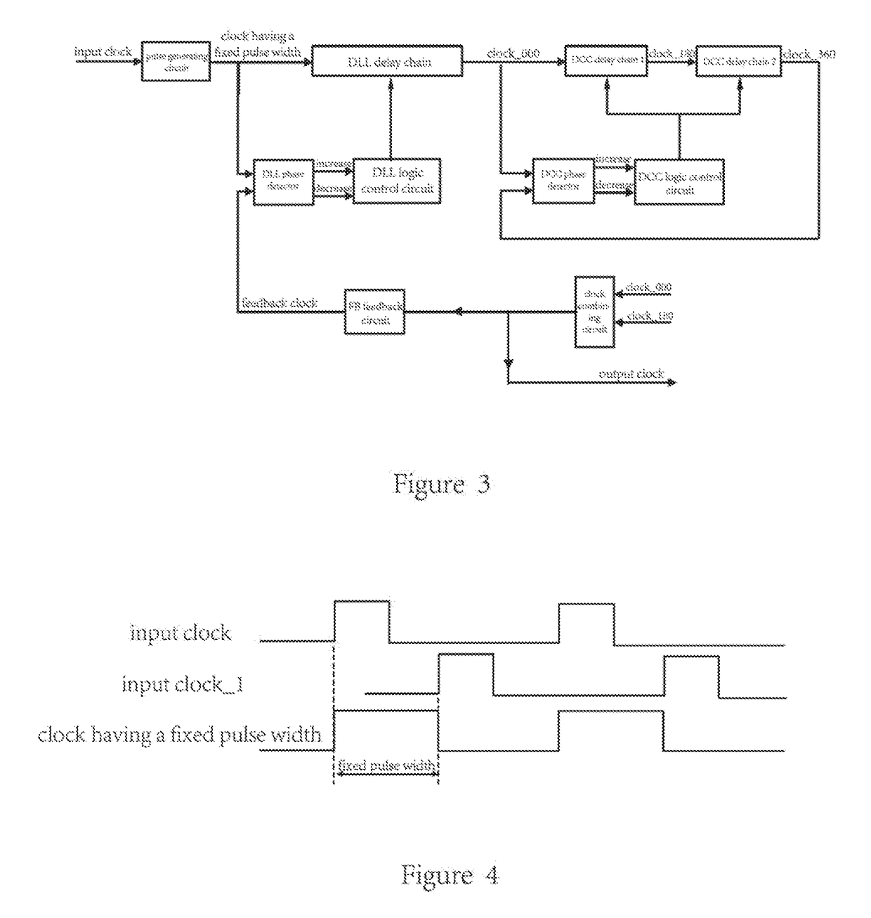
[0027]FIG. 3 shows a schematic diagram of a high-frequency delay-locked loop circuit structure according to one embodiment of the present invention. As shown in FIG. 3, the high-frequency delay-locked loop circuit includes a DLL circuit and a DCC circuit that are sequentially connected in series, and a pulse generating circuit; an input clock accesses the input of the DLL circuit via the pulse generating circuit; the pulse generating circuit is used for generating a clock having a fixed pulse width, the fixed pulse width is not smaller than the minimum pulse width required by the DLL circuit and the clock having the fixed pulse width is input into the DLL circuit. The operation principle of the pulse generating circuit will be described below with ...


PUM


Abstract

The present invention provides a high-frequency delay-locked loop and a clock processing method for the high-frequency delay-locked loop. The high-frequency delay-locked loop comprises a DLL circuit and a DCC circuit that are sequentially connected in series, and a pulse generating circuit used for generating a clock having a fixed pulse width. The fixed pulse width is a high-level width of the clock having the fixed pulse width and not smaller than a minimum pulse width required by the DLL circuit. The fixed pulse width enables a low-level width of the clock having the fixed pulse width to be not smaller than the minimum pulse width required by the DLL circuit. The clock having the fixed pulse width is input into the DLL circuit.

Description

TECHNICAL FIELD[0001]The present invention relates to a delay-locked loop, and more particularly relates to a high-frequency delay-locked loop and a clock processing method for the high-frequency delay-locked loop.BACKGROUND ART[0002]The delay-locked loop (DLL) technology, which is achieved by improving the PLL technology, is widely applied in the timing field. The DLL has inherited the phase lock technology for PLL circuit, but removed the oscillator section within the PLL circuit, which is replaced by a delay line whose delay amount can be controlled. Compared with the PLL, the DLL has no jitter accumulation, but has a shorter locking time and the advantage that the loop filter can be easily integrated and so on.[0003]A clock Duty Cycle Corrector (DCC) circuit is used for adjusting the duty cycle of a signal. The DCC can be used together with the DLL, thereby the duty cycle of an output signal can be adjusted to 50%.[0004]FIG. 1 is a schematic diagram of the circuit structure of a...

Claims


Application Information

Patent Timeline
IPC IPC(8): H03K7/08H03L7/081
CPCH03L7/0812H03K7/08H03L7/08
Inventor MINZONI, ALASSANDRO
Owner XI AN UNIIC SEMICON CO LTD
Why Eureka
Try Eureka