
Valve timing control for marine engine

a valve timing and marine technology, applied in marine propulsion, electrical control, vessel construction, etc., can solve the problems of affecting the performance of the engine, generating delay, and reacting slower to the valve timing mechanism, so as to achieve accurate follow-up commands, reduce the viscosity, and reduce the effect of delay

Inactive Publication Date: 2005-10-25
YAMAHA MARINE KK
View PDF61 Cites 20 Cited by
  • Summary
  • Abstract
  • Description
  • Claims
  • Application Information

AI Technical Summary

Benefits of technology

This solution enables the VVT system to maintain optimal performance by adjusting valve timing in real-time, reducing delays and improving engine efficiency and emission control across varying temperature conditions.

Problems solved by technology

However, if the viscosity is relatively high, the VVT mechanism reacts more slowly such that a delay is generated after a control signal from the ECU is received by the VVT mechanism.
Such a delay can, adversely affect the performance of the engine.
However, certain applications provide a limited space for the engine, such as in an outboard motor, or the engine compartment of a small watercraft.
For example, a typical outboard motor, does not offer any available space other than a location on its own engine body.
Therefore, a temperature of the engine, whether high or low, can significantly affect a temperature of the oil of the VVT mechanism.
An engine can be cold if it has not been operated for a significant period of time.
Thus, in a cold engine, the oil in the VVT mechanism has high viscosity, which causes the delay noted above until the engine is warmed up.
Thus, the oil in the VVT mechanism can remain cold and remain in the higher viscosity state for an unacceptable amount of time after the engine has been started.

Method used


Image

  • Valve timing control for marine engine
  • Valve timing control for marine engine
  • Valve timing control for marine engine

Examples


Embodiment Construction

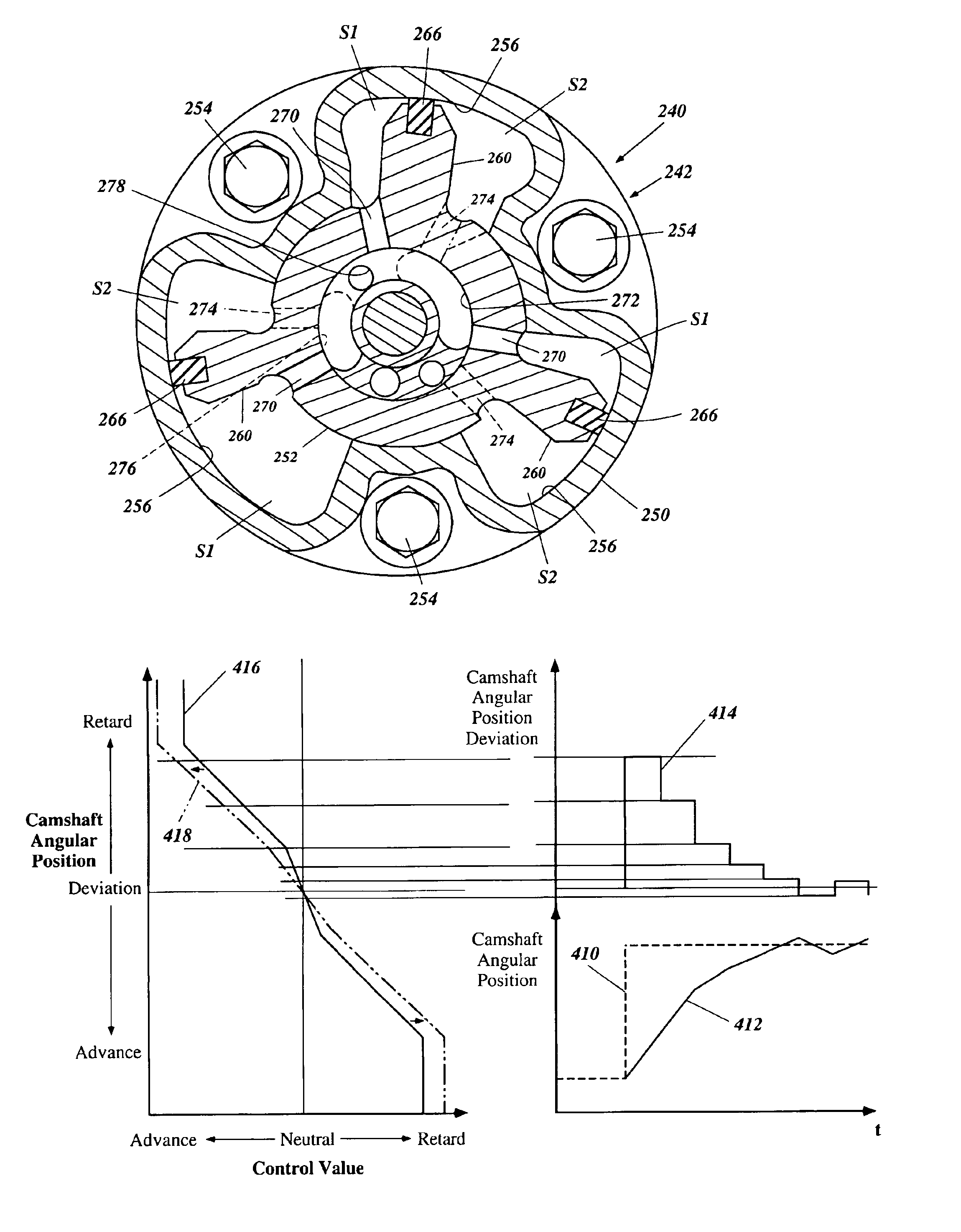
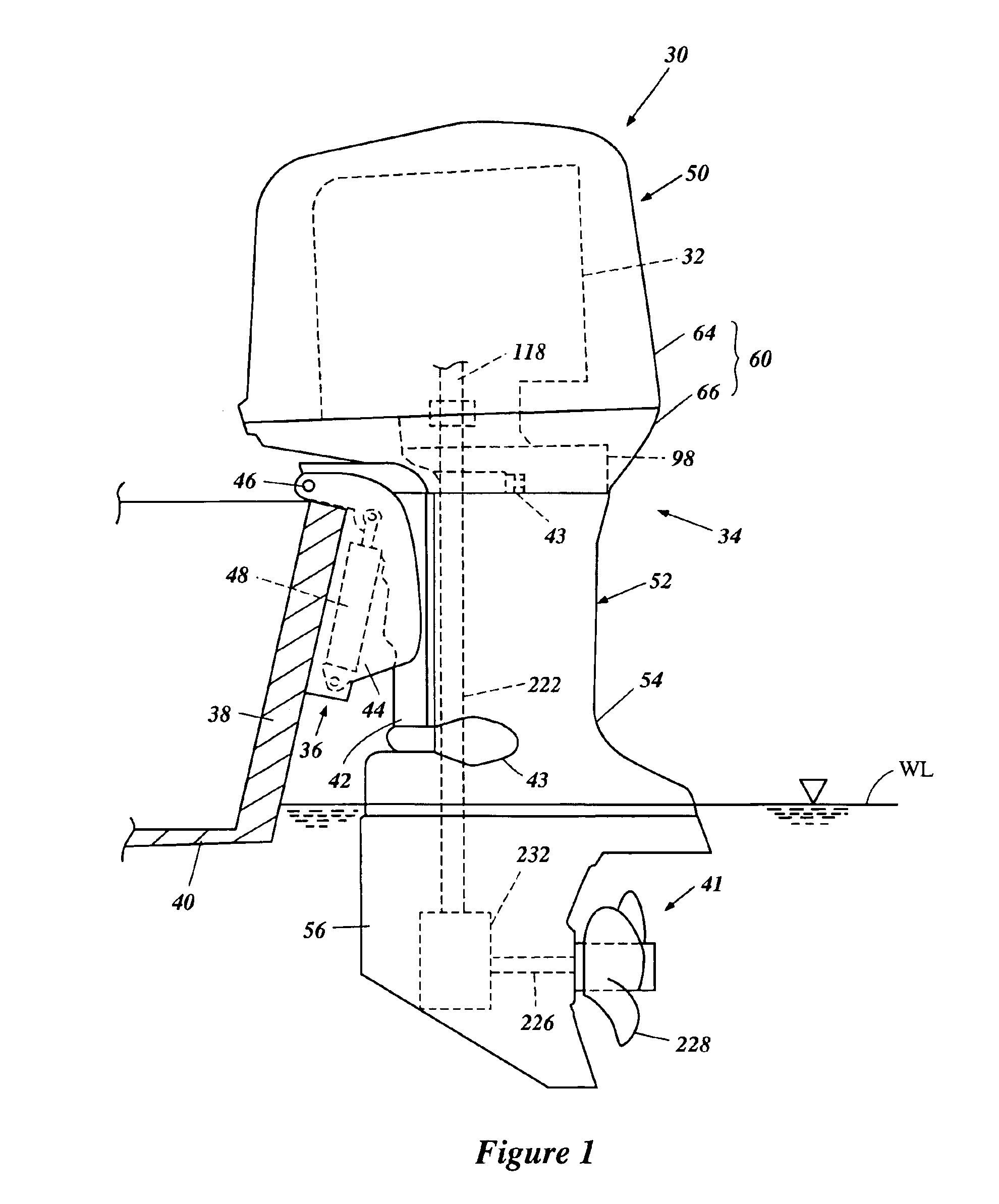
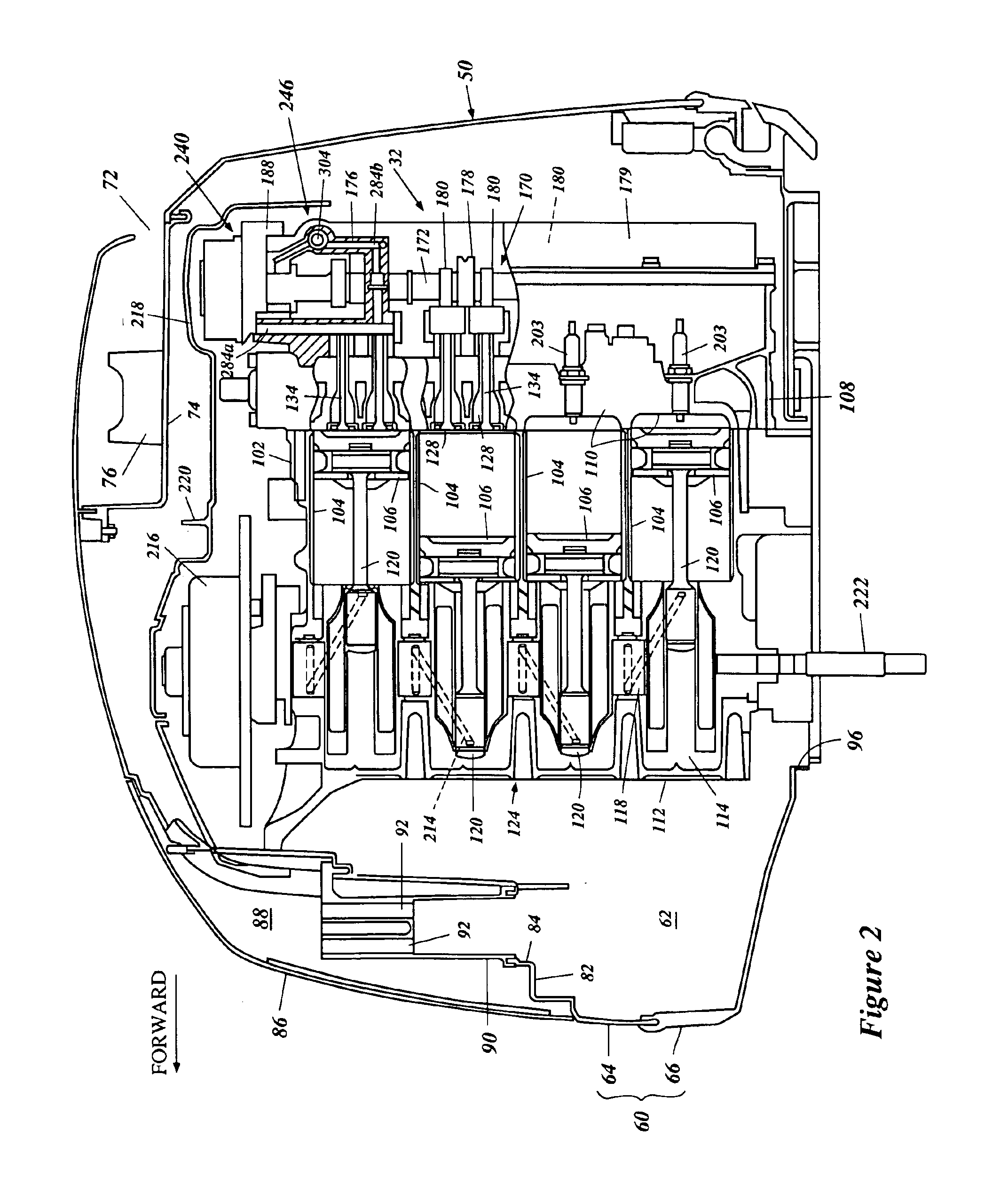
[0028]With reference to FIGS. 1-5, an overall construction of an outboard motor 30 that employs an internal combustion engine 32 configured in accordance with certain features, aspects and advantages of the present invention is described below. The engine 32 has particular utility in the context of a marine drive, such as the outboard motor, and thus is described in the context of an outboard motor. The engine 32, however, can be used with other types of marine drives (i.e., inboard motors, inboard / outboard motors, etc.) and also certain land vehicles. Furthermore, the engine 32 can be used as a stationary engine for some applications that will become apparent to those of ordinary skill in the art.

[0029]In the illustrated arrangement, the outboard motor 30 generally comprises a drive unit 34 and a bracket assembly 36. The bracket assembly 36 supports the drive unit 34 on a transom 38 of an associated watercraft 40 and places a marine propulsion device 41 in a submerged position with...


PUM


Abstract

An engine for a marine drive has a combustion chamber. An engine body of the engine defines intake and exhaust ports communicating with the combustion chamber. An air induction system communicates with the combustion chamber through intake ports. An exhaust system communicates with the combustion chamber through the exhaust ports. Intake valves move between an opening position and a closing position of the intake ports. Exhaust valves move between an opening position and a closing position of the exhaust ports. Camshafts actuate the intake and the exhaust valves. A hydraulic VVT mechanism changes an actuating timing of the camshaft at which the camshaft actuates the intake valves or the exhaust valves. An ECU controls the VVT mechanism based upon a control characteristic. A temperature sensor, such as an oil temperature sensor, a water temperature sensor and an engine body temperature sensor, senses a temperature of oil of the VVT or a temperature relating to the temperature of the oil and sends a temperature signal to the ECU. The ECU adjusts the control characteristic when the temperature is lower than a preset temperature.

Description

PRIORITY INFORMATION[0001]This application is based on and claims priority to Japanese Patent Application No. 2001-199088, filed Jun. 29, 2001, the entire contents of which is hereby expressly incorporated by reference.BACKGROUND OF THE INVENTION[0002]1. Field of the Invention[0003]The present invention is directed to a valve timing control for an engine, and more particularly to an improved valve timing control for an engine that includes a variable valve timing mechanism.[0004]2. Description of Related Art[0005]Engines, for example, but without limitation, such as those used in marine drives including outboard motors, drive propulsion devices. The propulsion device typically is a propeller and is submerged when an associated watercraft rests on a body of water. The engine can be either a two-cycle engine or a four-cycle engine. Recently, however, many outboard motors have been constructed with four-cycle engines which provide better emission control.[0006]Typically, a four-cycle e...

Claims


Application Information

Patent Timeline
Patent Type & Authority Patents(United States)
IPC IPC(8): F02B75/20F02B61/00F01L1/344F02B75/00F02B61/04F02D13/02F02B75/18F01L1/34F01L13/00F02D41/04F02D45/00
CPCF01L1/3442F02B61/045F02B75/20F02D13/0253F01L1/022B63B2770/00Y10T74/2102F01L1/024F01L2001/0537F01L2001/3443F01L2001/34433F01L2101/00F01L2800/00F02B2075/1816Y02T10/18B63H20/24F01L2301/00Y02T10/12
Inventor KATAYAMA, GOICHI
Owner YAMAHA MARINE KK
Learn More