Eureka AIR delivers breakthrough ideas for toughest innovation challenges, trusted by R&D personnel around the world.

Thermally assisted magnetic recording system and method of writing using magnetic and thermal gradients

a recording system and thermal gradient technology, applied in combination recording, data recording, instruments, etc., can solve the problems of bit magnetization decay, difficult to maintain the transducer centering over the very narrow data track during read and write operations, and increased areal density of magnetic media, so as to prevent thermal instabilities from degrading the new magnetization state

Inactive Publication Date: 2005-09-27
WESTERN DIGITAL TECH INC
View PDF9 Cites 39 Cited by
  • Summary
  • Abstract
  • Description
  • Claims
  • Application Information

AI Technical Summary

Benefits of technology

[0011]It is another object of the present invention to dislose a magnetic recording system combining a magnetic write field gradient and a thermal gradient to write data on a magnetic disk having a high magneto-crystalline anisotropy resulting in an increased areal recording density.
[0018]To avoid thermal instabilities of the stored magnetic data, a minimal stability ratio of stored magnetic energy KUV to thermal energy kBT of KuV / kBT of about 60 is required, where KU is the magneto-crystalline anisotropy of the magnetic media, V is the magnetic switching volume, kB is the Boltzmann constant and T is the temperature of the media. Having successfully switched the magnetic media by heating the transition region so as to exceed its write energy threshold, it is necessary to rapidly cool the transition region in order to prevent thermal instabilities from degrading the new magnetization state. By arranging to substantially overlap the trailing edges of the temperature and magnetic field gradients produced by the VSAL light pulse and the write current pulse through the metallic reflective layer, respectively, the transition region cools by diffusive processes sufficiently rapidly to maintain its magnetization.

Problems solved by technology

However, there is a problem with the prior art magnetic recording systems and the magnetic media as areal density is further increased to densities greater than about 100 Gbits / in2.
As the track density increases, it becomes increasingly difficult to maintain the transducer centered over the very narrow data track during read and write operations.
As the bit density along the track increases, a more fundamental problem arises due to the small size of the bits causing instability of the bit magnetization due to thermal fluctuations.
This results in a decay of the bit magnetization and loss of the stored data.

Method used


Image

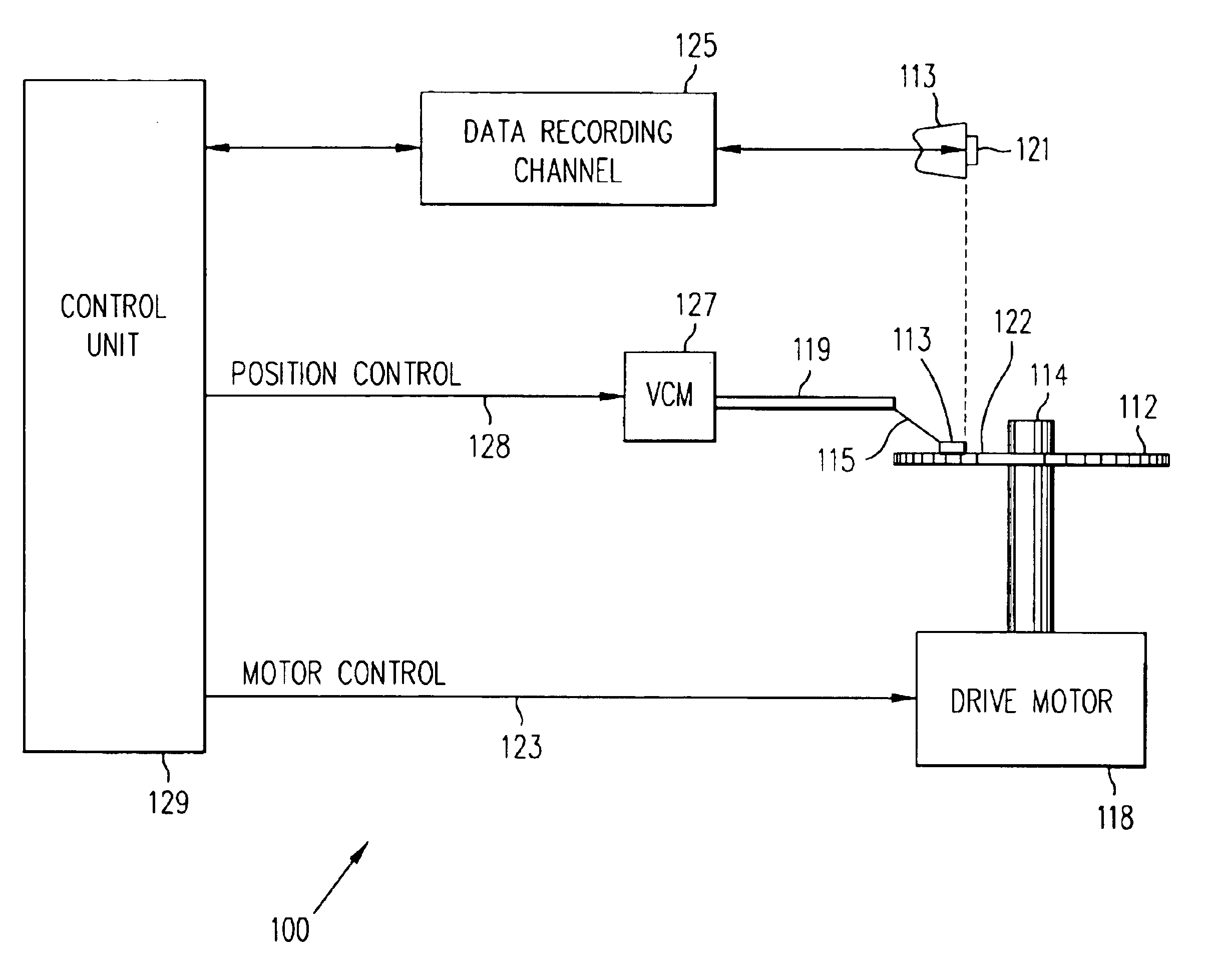
  • Thermally assisted magnetic recording system and method of writing using magnetic and thermal gradients
  • Thermally assisted magnetic recording system and method of writing using magnetic and thermal gradients
  • Thermally assisted magnetic recording system and method of writing using magnetic and thermal gradients

Examples


second embodiment

[0066]FIG. 6a shows the layer structure of a thermal spring magnetic recording media 600 for use with the read / write head of the present invention. The thermal spring media 600 comprises a bilayer 601 formed of a thick first magnetic layer 606 of high magneto-crystalline anisotropy KU1, low Curie temperature TC1 material and an adjacent thin second magnetic layer 608 of low KU2, high saturation magnetization MS2, high Curie temperature TC2 material in laminar contact with the first layer. The first magnetic layer 606 is made of the L10 phase of Fe—Pt—Ni where a small amount of Ni is added to reduce TC to the desired level. Table 1 is data showing the effect of Ni concentration on the magneto-crystalline anisotropy KU and the Curie temperature TC of L10 materials. The first magnetic layer 606 of Fe—Pt—Ni has a thickness of approximately 60 Å. Alternatively, the first magnetic layer 606 may be formed of other granular, high anisotropy alloys such as the L1O phases of Fe—Pt, Co—Pt and ...

third embodiment

[0070]FIG. 6b shows the layer structure of a thermal spring magnetic recording media 620 for use with the read / write head of the present invention. The thermal spring media 620 comprises a thick first magnetic layer 622 of a granular L10 phase of Fe—Pt—Ni having a thickness of approximately 60 Å and an adjacent thin stack 624, in laminar contact with the first magnetic layer, made of a plurality of repetitions, preferably 1-4 repetitions, of second magnetic layers 626 of Co having a thickness in the range of 10-50 Å interleaved with nonmagnetic layers 628 of Pd, or alternatively Pt, having a thickness in the range of 1-25 Å. Alternatively, the first magnetic layer 622 may be formed of other granular, high anisotropy alloys such as the L10 phases of Fe—Pt, Co—Pt and Co—Pd. The second magnetic layers 626 may be made of ferromagnetic cobalt-based alloys such as Co—Pt—Cr—B, Co—Pt—Cr, Co—Cr, Cr—Pt—Cr—Nb, Co—Pd—Cr—Nb, Co—Pd—Cr—B and Co—Pd—Cr. The first magnetic layer 622 and the stack 624...


PUM

PropertyMeasurementUnit
sizeaaaaaaaaaa
wavelengthaaaaaaaaaa

Abstract

A magnetic recording system is provided having a write head employing a combination of magnetic write field gradient and thermal gradient to write data on a ‘thermal spring’ magnetic recording media. The write head comprises a magnetic element using a write current to induce a magnetic write field at the magnetic media and a thermal element using a very small aperture laser to heat a portion of the media. The thermal spring magnetic media comprises [comprises] first and second stacks providing two exchange coupled ferromagnetic layers having different Curie temperatures [The first stack has a high magneto-crystalline anisotropy, a relatively low saturation magnetization and a low Curie temperature.] [The second stack has a relatively low magneto-crystalline anisotropy, a high saturation magnetization and a high Curie temperature.] The magnetic field gradient and the thermal gradient are arranged to substantially overlap at the trailing edge of the heated portion of the magnetic media allowing data at high density with high thermal stability to be recorded on the rapidly cooling thermal spring magnetic recording media.

Description

CROSS REFERENCE TO RELATED APPLICATION[0001]U.S. patent application Ser. No. 09 / 874,100, entitled ‘THERMAL SPRING’ MAGNETIC RECORDING MEDIA FOR WRITING USING MAGNETIC AND THERMAL GRADIENTS, was filed on the same day and owned by a common assignee.BACKGROUND OF THE INVENTION[0002]1. Field of the Invention[0003]The present invention relates to magnetic recording systems for writing information signals on a magnetic medium and, in particular, to a magnetic recording system employing a combination of magnetic write field gradient and thermal gradient to increase the areal density of magnetic recording, and to a ‘thermal spring’ magnetic recording media for recording information with such systems.[0004]2. Description of the Related Art[0005]Moving magnetic storage devices, especially magnetic disk drives, are the memory device of choice. This is due to their expanded non-volatile memory storage capability together with a relatively low cost. Thin film magnetic read / write heads are used f...

Claims


Application Information

Patent Timeline
Patent Type & Authority Patents(United States)
IPC IPC(8): G11B5/02G11B5/55G11B5/596
CPCG11B5/02G11B5/5521G11B5/59683
Inventor COFFEY, KEVIN ROBERTFONTANA, JR., ROBERT EDWARDTHIELE, JAN-ULRICH
Owner WESTERN DIGITAL TECH INC
Why Eureka
Eureka Blog
Learn More