
Method and apparatus for balancing the emission current of neutralizers in ion thruster arrays

a technology of neutralizers and ion thrusters, applied in mechanical apparatus, machines/engines, plasma techniques, etc., can solve the problems of ion propulsion systems that are very low thrust when compared with chemical propulsion systems, relative recent implementation of practical applications, and delay in the development of practical applications, etc., to achieve mass saving and reduce the overall packaging mass

Inactive Publication Date: 2005-09-27
THE BOEING CO
View PDF8 Cites 13 Cited by
  • Summary
  • Abstract
  • Description
  • Claims
  • Application Information

AI Technical Summary

Benefits of technology

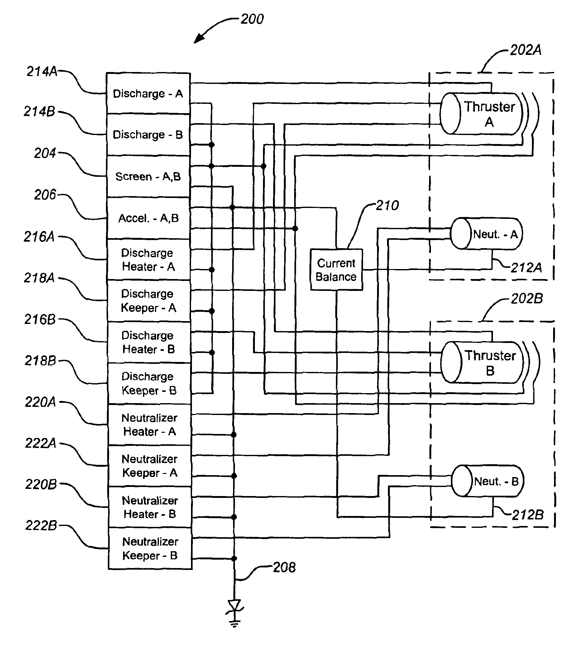
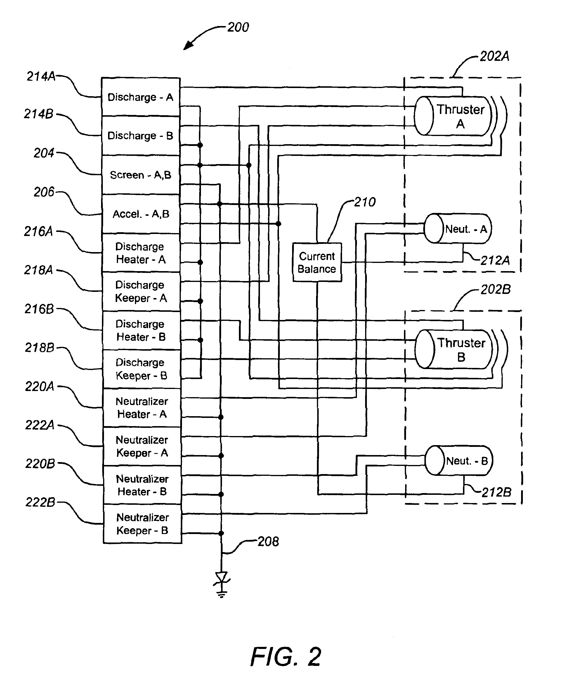
The present invention allows a single power source to power multiple ion thrusters in an array, using voltage-regulated supplies for certain elements and current-regulated supplies for others. This results in significant mass savings and reduces the complexity of the system. A current balance circuit is used to ensure balanced current between the thrusters, while some elements require current-regulated power supplies for proper regulation. Overall, the invention simplifies the design and operation of ion propulsion systems, reducing expense and complexity.

Problems solved by technology

Although the principle of ion propulsion was established many decades ago, it has only relatively recently been implemented in practical applications.
The delay in development of practical applications may be due, in part to the fact that, although they are efficient, ion propulsion systems develop very low thrust when compared with chemical propulsion systems.
The neutralizer cathode, commonly a hollow cathode, is generally life limited by its operating temperature; the higher the operating temperature, the shorter the operating life of the cathode (and accordingly, the shorter the operating life of the thruster).
Consequently, this adds considerably to the mass required to drive the ion thruster array.

Method used


Image

  • Method and apparatus for balancing the emission current of neutralizers in ion thruster arrays
  • Method and apparatus for balancing the emission current of neutralizers in ion thruster arrays
  • Method and apparatus for balancing the emission current of neutralizers in ion thruster arrays

Examples


Embodiment Construction

[0022]In the following description of the preferred embodiment, reference is made to the accompanying drawings which form a part hereof, and in which is shown by way of illustration a specific embodiment in which the invention may be practiced. It is to be understood that other embodiments may be utilized and structural changes may be made without departing from the scope of the present invention.

1. Overview

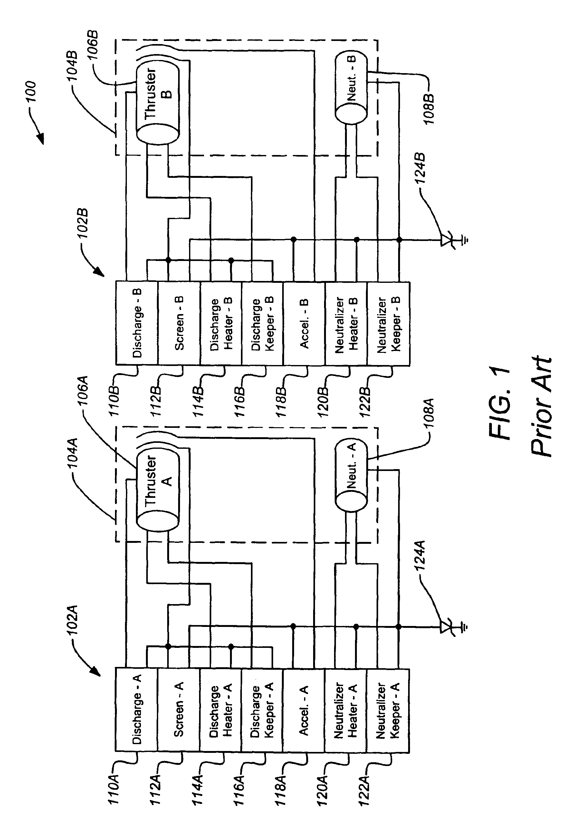
[0023]Because it is important to minimize the operating temperature of the neutralizer cathodes, as discussed above, it is not reasonable to simply combine all the PPUs in a single device with common power supplies to each ion thruster component of a plurality of ion thrusters in an array. In such a thruster array, the common return to the PPU from the neutralizer cathodes of the ion thrusters would be electrically connected to each other. As a result, the total electron emission would not be balanced equally between the neutralizer cathodes. Consequently, the operating temperatu...


PUM


Abstract

An apparatus and method for balancing the emission current of neutralizers in ion thruster arrays is disclosed that allows a single power processing unit (PPU) to be used to drive the array. A typical embodiment includes at least one voltage-regulated power supply, each voltage-regulated power supply for driving a common element in each of the plurality of ion thrusters, the common element in each of the plurality of ion thrusters being coupled together at a common point, and a current balance circuit for providing a substantially balanced current to each neutralizer cathode of the plurality of ion thrusters by providing a voltage to the neutralizer cathodes relative to the common point.

Description

BACKGROUND OF THE INVENTION[0001]1. Field of the Invention[0002]The present invention relates to apparatuses and methods for optimizing the operation of ion thruster arrays. Particularly, the present invention relates to apparatuses and methods for balancing the emission current of neutralizers in ion thruster arrays.[0003]2. Description of the Related Art[0004]Ion propulsion generally involves employing an ionized gas accelerated electrically across charged grids to develop thrust. The electrically accelerated particles can achieve very high speeds. The gas used is typically a noble gas, such as xenon. The principle advantage afforded by ion propulsion systems over conventional chemical propulsion systems is their very high efficiency. For example, with the same amount of fuel mass an ion propulsion system can achieve a final velocity as much as ten times higher than that obtainable with a chemical propulsion system. Although the principle of ion propulsion was established many dec...

Claims


Application Information

Patent Timeline
Patent Type & Authority Patents(United States)
IPC IPC(8): F03H1/00H05H1/00
CPCF03H1/0025
Inventor BEATTIE, JOHN ROBERTSONI, PRAKASH C.
Owner THE BOEING CO
Learn More