
Theft-Protected Screw Part

a screw and protection technology, applied in the direction of screws, nuts, bolts, etc., can solve the problems of easy thief to steal the wheels, the screw parts thus produced are always slightly heavier, etc., and achieve the effect of easy removal or destruction, better connection of insert and projection, and larger torqu

Active Publication Date: 2010-12-23
ABC UMFORMTECHN
View PDF8 Cites 5 Cited by
  • Summary
  • Abstract
  • Description
  • Claims
  • Application Information

AI Technical Summary

Benefits of technology

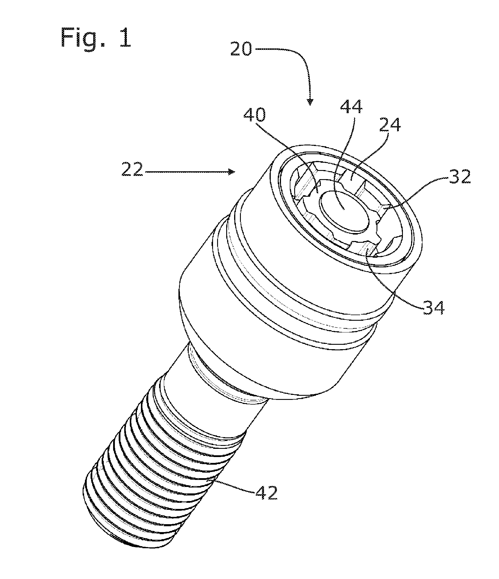
[0009]Because of the projection, the head, the shaft and the screw portion are not weakened anymore, the head can thus be shorter and the bottom closer to the screw portion, the screw part can thus be formed shorter than in accordance with the prior art. This saves weight. The weight saved is such that a total weight of the finished theft-protected screw part is obtained which corresponds to that of the normal nut or normal screw. This results in an economization with regard to mass which is beneficial for the driving behavior of the vehicle. As is known, saving mass on the wheels is even more efficient that saving mass on the car body.
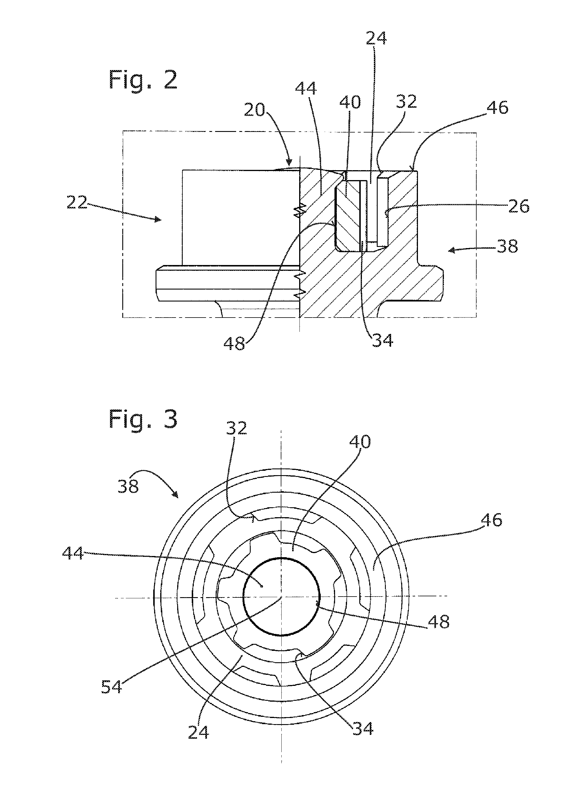
[0011]In an advantageous development, the hole of the insert is cylindrical or non-circular. A round hole makes an alignment by rotation possible. A non-circular hole makes an alignment of the insert and / or a better connection of the insert and the projection possible. If the hole is configured to be non-circular, it may be, for example, formed as an internal toothing with n teeth, so that n different angular positions are predetermined mechanically. The radial outer surface of the projection may also have circular cross-sections or non-circular cross-sections. The connection already described above, which is capable of absorbing larger torques, can be obtained in the case of non-circular cross-sections. An alignment is also possible. Circular holes can be combined with a non-circular cross-section of the projection, however, the hole and the projection preferably are circular or non-circular with approximately the same form, for example, toothed, oval or polygonal.

Problems solved by technology

Such wheels can and should be mounted and removed by means of normal wrenches, however, this also makes it easier for a thief to steal the wheels.
It was now found, however, that screw parts thus produced are always slightly heavier than the original screw part configured without theft protection.

Method used


Image

  • Theft-Protected Screw Part
  • Theft-Protected Screw Part
  • Theft-Protected Screw Part

Examples


Embodiment Construction

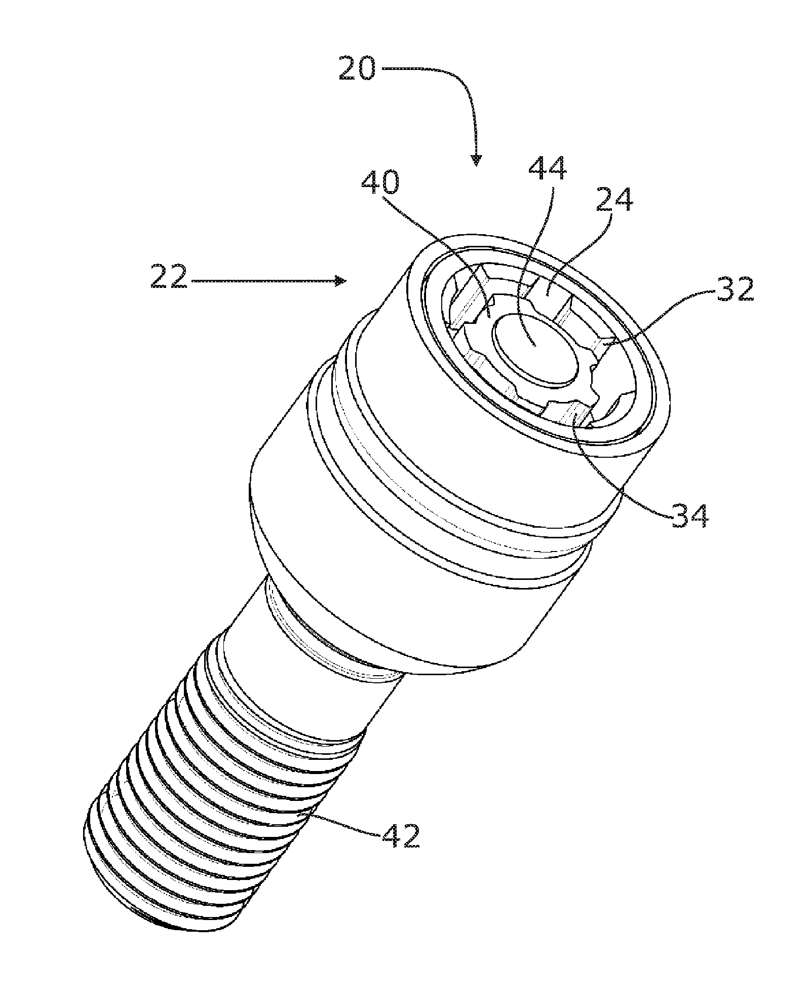
[0023]The theft-protected screw part according to the exemplary embodiment has the shape of a screw. It comprises a free end portion 20 terminating a head 22 of the screw part at an axial end. A depression 24 extends from this free end portion in the axial direction, the depression being limited, as seen radially from the outside towards the inside, by an outer edge 26, a bottom 28 and an inner edge 30. It is open towards the free end portion 20. The outer edge 26 is non-circular, it comprises projections and recesses disposed in an encoded way, with outer stop faces 35 being formed by them. The inner edge 30 also has a non-circular form, it also comprises projections and recesses disposed in an encoded way, with inner stop faces 34 being formed by them. A wrench, which is not shown here anymore, is in engagement with these stop faces 32, 34 when it is inserted into the depression 24. Such a wrench is formed similar to the tool 36 which is shown in FIG. 9 and which can be used durin...


PUM


Abstract

The theft-protected screw part in the form of a nut or a screw has a free end region and a ring-shaped depression formed at the end region for the engagement of a wrench for rotation the screw part. Viewed from radially outside to radially inside, the depression is delimited by an outer edge, a bottom and an inner edge. The outer edge forms outer abutment surfaces and the inner edge forms inner abutment surfaces for the wrench. The screw part is composed of a main part and an insert. The main part has a protrusion, which is located within the inner edge. The insert is designed in a ring shape, has a hole for accommodating the protrusion and forms the inner abutment surfaces.

Description

BACKGROUND OF THE INVENTION[0001]The invention relates to a theft-protected screw part and a method for producing it.BRIEF DESCRIPTION OF RELATED ART[0002]Such a theft-protected screw part is known from DE 199 02 192 A1 by the applicant. A similar theft-protected screw part is known from DE 1 041 302C. Other theft-protected screw parts are described in DE 1 480 817 A and DE 295 10 069 U1.[0003]Theft-protected screw part are used, among other things, for protecting vehicle wheels, in particular vehicle rims, against theft. Vehicle manufacturers usually deliver their vehicles with the wheels being fixed by means of normal, commercially available screws or nuts. Such wheels can and should be mounted and removed by means of normal wrenches, however, this also makes it easier for a thief to steal the wheels. Special screw parts are already known which have a specially formed head that cooperates only with a special wrench. This can provide an effective impediment to the wheel being screw...

Claims


Application Information

Patent Timeline
IPC IPC(8): F16B19/10
CPCF16B41/005F16B23/0007
Inventor LANNEREE, DANIEL
Owner ABC UMFORMTECHN
Learn More