Rear part of an aircraft comprising a structure for supporting engines, extending through the fuselage and connected thereto by at least one connecting rod

Inactive Publication Date: 2011-09-22
AIRBUS OPERATIONS (SAS)
View PDF6 Cites 4 Cited by
  • Summary
  • Abstract
  • Description
  • Claims
  • Application Information

AI Technical Summary

Benefits of technology

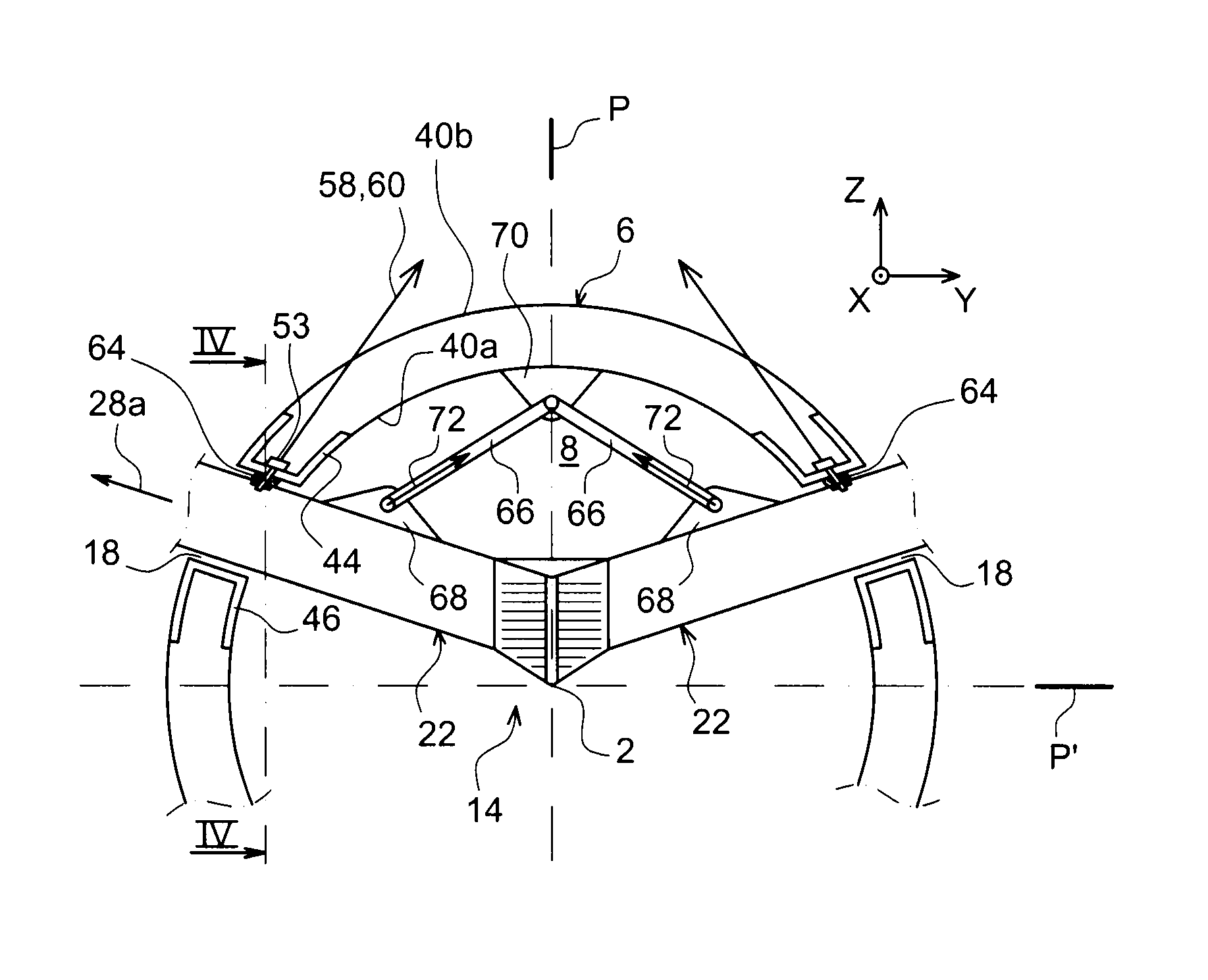
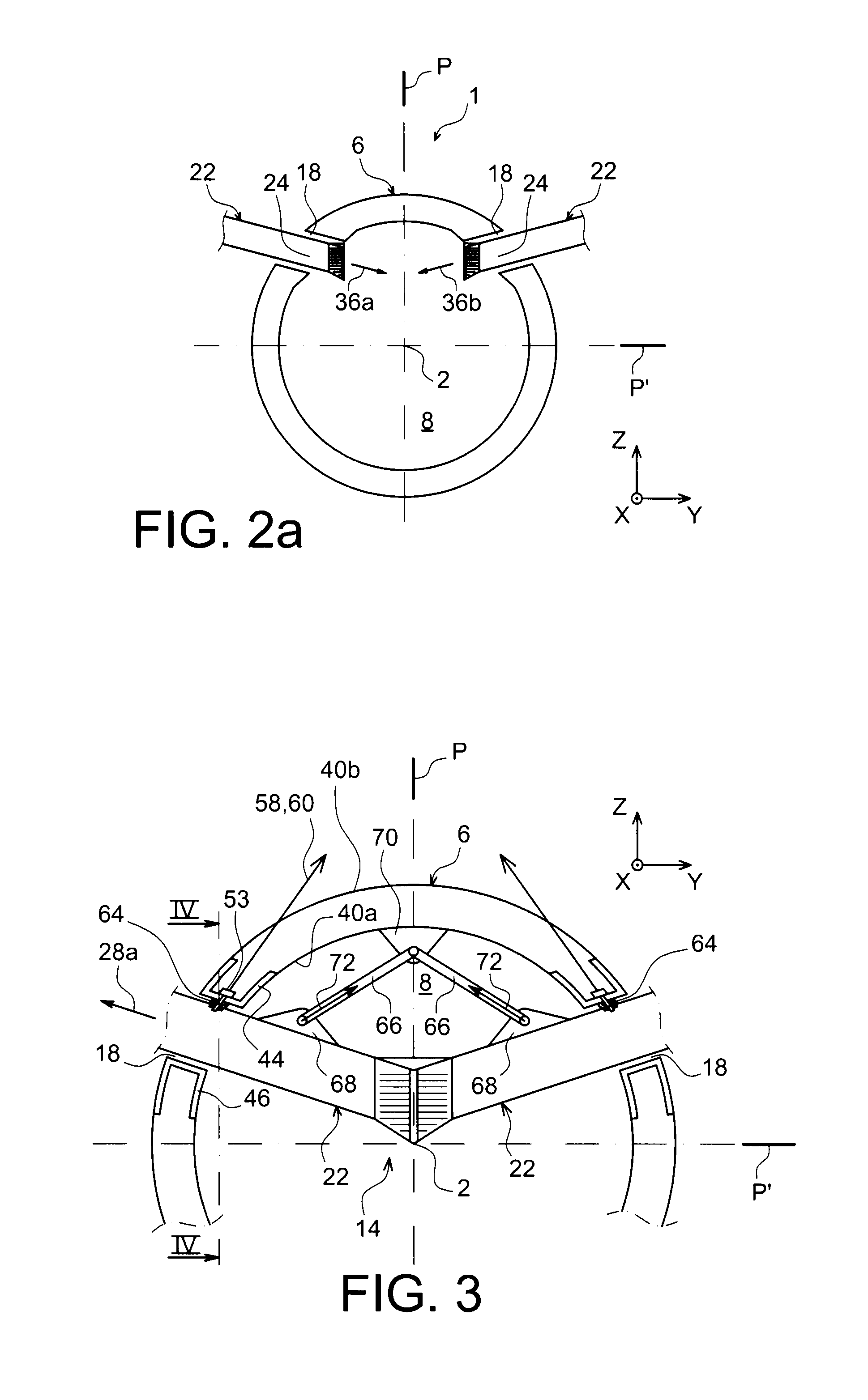
[0013]Thus, the original design proposed by the present invention advantageously makes it possible to minimize the intensity of the forces passing through the fuselage opening casings, allowing the latter to have smaller dimensions than those previously seen. Indeed, part of the forces coming from the engine and oriented towards the fuselage no longer uses the opening casings of the fuselage, but passes through the connecting rods specific to the present invention, the first aim of which is therefore to introduce motive forces at points of the fuselage spaced away from the openings. The concentration of stresses within the opening casings of the fuselage is therefore substantially minimized.
[0014]Moreover, to minimize the concentration of stresses within the support structure of the engines, at the fuselage openings, it is preferably done so that the first connecting rod end is also mounted on that support structure, away from the openings. The structure less locally stressed can thus have smaller dimensions, for non-negligible mass savings.
[0022]Preferably, at least two effort recovery connecting rods are provided articulated on a plate, itself articulated on the support structure or on the fuselage. This makes it possible to balance the efforts transmitted by each of the connecting rods.
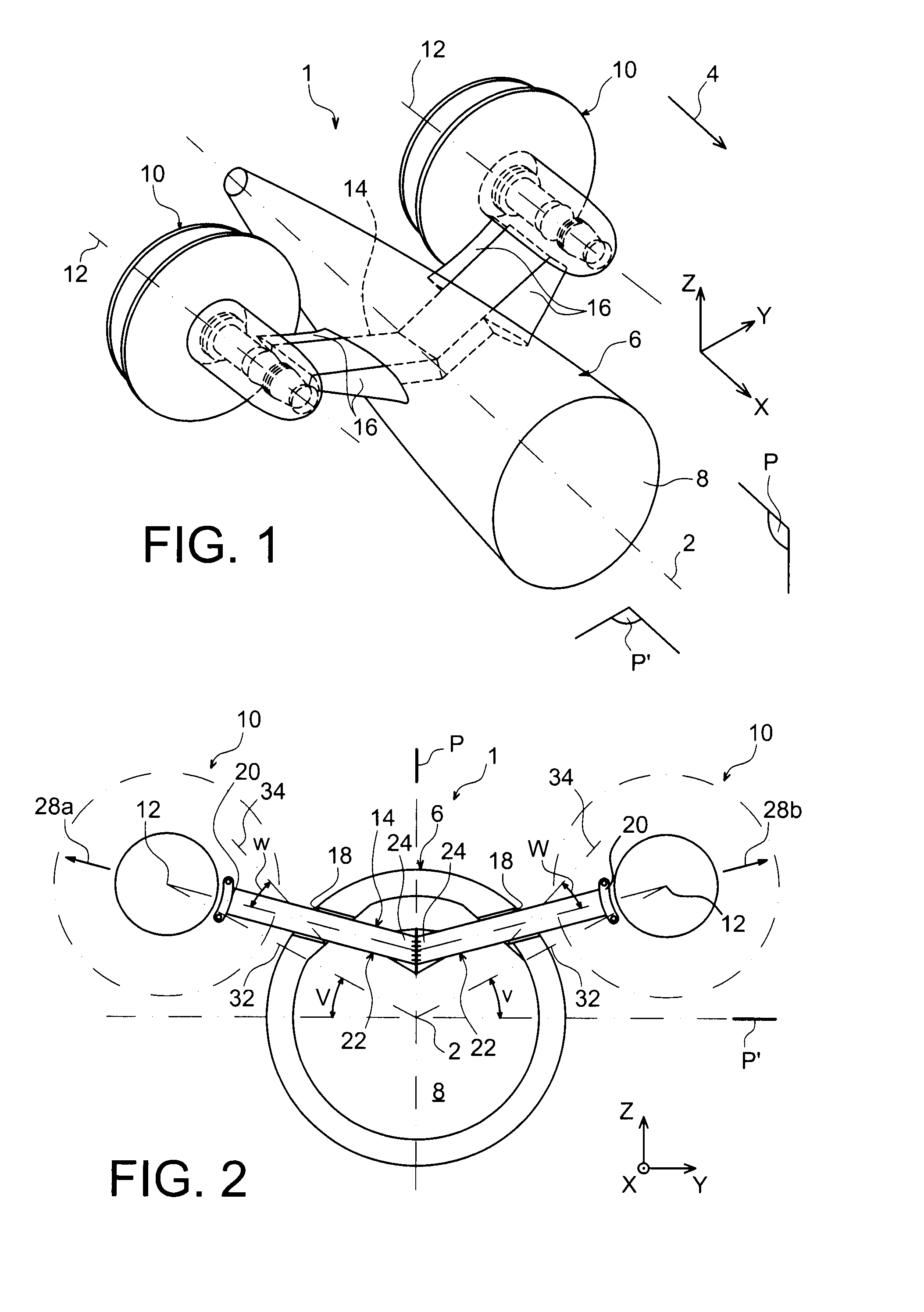
[0024]Thus, this makes it possible to greatly facilitate the assembly and disassembly operations of the support structure of the engines, since it is currently done from two separate half-structures, assembled to each other reversibly. Each of these two half-structures can thus be manipulated independently of the other during an assembly / disassembly, making the work easier for operators. In particular, each support half-structure only requires going through a single fuselage opening, advantageously involving a noticeable simplification for the operators, both during the initial assembly and during replacement of the support structure.
[0026]Naturally, this last advantage is also observed during an operation to disassemble the support structure from the engines, given that each engine can be placed while remaining attached to its associated support half-structure.
[0027]Lastly, another advantage resulting from the embodiment with two half-structures lies in the possibility of tilting them relative to each other, when they are seen from the front, in particular so that they form a V.

Problems solved by technology

This amounts to drag, which penalizes the overall aerodynamic performance of the aircraft.
This results in the need to overdimension the assembly, in particular the opening casings and the surrounding fuselage portions, to the detriment of the overall mass of the aircraft.

Method used


Image

  • Rear part of an aircraft comprising a structure for supporting engines, extending through the fuselage and connected thereto by at least one connecting rod
  • Rear part of an aircraft comprising a structure for supporting engines, extending through the fuselage and connected thereto by at least one connecting rod
  • Rear part of an aircraft comprising a structure for supporting engines, extending through the fuselage and connected thereto by at least one connecting rod

Examples


second embodiment

[0096]FIGS. 6 to 8 show another preferred embodiment in which each of the first and second fastening means assumes the form of a second embodiment, the effort recovery connecting rods 66 being kept here.

[0097]Indeed, the first fastening means, which will be the only ones described since they are identical and symmetrical to the second fastening means, now comprise a hinge-type connection between the rear face 52′ of the half-structure 22 and the rear face 42′ of the casing. To that end, an axis 80 parallel to the direction 28a connects a yoke 82 and a fitting 84 respectively integral with opposite faces 42′, 52′, or vice versa. Preferably, the other faces of the half-structure 22 and the casing 50 are still without connecting means, but are still opposite in pairs.

[0098]The connection obtained ensures the recovery of the efforts along the direction orthogonal to the direction 28a, in a plane YZ, as diagrammed by arrow 86, as well as the recovery of efforts along the direction orthog...

third embodiment

[0099]FIGS. 9 and 10 show another preferred embodiment in which each of the first and second fastening means assumes the form of a third embodiment, the effort recovery connecting rods 66 here also being kept.

[0100]The first and second fastening means having a substantially identical design, and being symmetrical relative to the plane P, only the first means will be described below.

[0101]In this third embodiment, the first fastening means first comprise at least one blocking element of the support structure, under compression loading while bearing on one hand on the first casing 50, and on the other hand of the support half-structure 22. In this configuration, the first fastening means are at least partially formed using blocking elements that work in compression, and no longer in traction as was the case in the traditional elements of the prior art, of the bolt type or a similar type. This results in an ease of placement of these blocking elements, because the latter can be situate...


PUM


Abstract

A rear part of an aircraft including a support structure for supporting engines, extending through the fuselage, through a first opening and a second opening. A connection structure connects the support structure to the fuselage, including a first connection mechanism connecting the support structure to a first casing forming the first opening and a second connection mechanism connecting the support structure to a second casing forming the second opening. The connection structure also includes at least one effort recovery connecting rod, the first end of which is mounted on the support structure and the opposite end is mounted on the fuselage, at a distance from the first and second openings.

Description

TECHNICAL FIELD[0001]The present invention generally relates to a rear part of an aircraft, equipped with engines fastened on the fuselage thereof.BACKGROUND OF THE INVENTION[0002]To make such a rear aircraft part, it has been proposed, in the prior art, to insert an attachment mast between the fuselage and each engine. In that configuration, the mast is fixed directly on the fuselage. To ensure a satisfactory transfer of motive force towards the fuselage, significant dimensioning is necessary for the mast, the part of the fuselage supporting it, and the fastening means inserted between those elements. This amounts to drag, which penalizes the overall aerodynamic performance of the aircraft.[0003]Another solution consists of providing a support structure for the engines going through the fuselage, as well as the inner space of the aircraft defined by said fuselage. At the level of its passage through the two fuselage openings, the through structure is spliced to the fuselage using a...

Claims


Application Information

Patent Timeline
IPC IPC(8): B64D27/02B64D27/26
CPCB64D27/14Y02T50/66B64D2027/005B64D29/04Y02T50/60
Inventor LAFONT, LAURENTJOURNADE, FREDERICJALBERT, DELPHINEBARDOU, ETIENNE
Owner AIRBUS OPERATIONS (SAS)
Why Eureka
Try Eureka