
Process and equipment for manufacture of advanced composite structures

a composite structure and advanced technology, applied in the direction of weaving, bandages, other domestic articles, etc., can solve the problem of not offering the potential for dramatic improvement in structural performan

Inactive Publication Date: 2005-09-06
DIEFFENBACHER GMBH & CO KG
View PDF8 Cites 36 Cited by
  • Summary
  • Abstract
  • Description
  • Claims
  • Application Information

AI Technical Summary

Benefits of technology

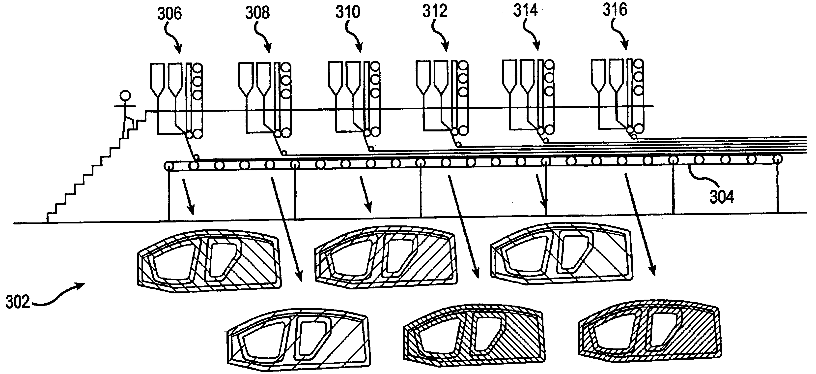
[0008]Advantages to this invention are that it addresses fundamental elements required if a breakthrough in affordable high performance and high volume advanced composite automotive structures are to become a reality. Issues this invention successfully address are: 1) the need for minimal touch labor between part design and near-finished part, 2) highly repeatable, tailorable, versatile, and controllable processes, 3) minimization of scrap materials during fabrication, 4) in-line process monitoring and control (to minimize post-inspection and scrapped finished components), 5) delivery of “advanced composite” performance via aligned “continuous”-like fibrous reinforcement, 6) ability to handle the lay-up of many laminate architectures using the same equipment and switch between lay-ups readily to manage and balance production leveling for a range of model variants etc., and 7) in-line approach to applying other materials and value added functionality such as sound and vibration dampening, paintless coloring and finish, integral trim surfaces, among other benefits.
[0024]Another object of the present invention is to utilize flexibility in terms of risk, starting materials, and quality achieved.

Problems solved by technology

While material stiffness can be compensated to some degree via the shaping of the components to enhance structural stability, randomly reinforced composite materials currently being used by the automotive industry have even less stiffness and therefore do not offer the potential for dramatic improvements in structural performance.

Method used


Image

  • Process and equipment for manufacture of advanced composite structures
  • Process and equipment for manufacture of advanced composite structures
  • Process and equipment for manufacture of advanced composite structures

Examples


Embodiment Construction

)

[0034]Reference will now be made in detail to the preferred embodiments of the present invention, examples of which are illustrated in the accompanying drawings.

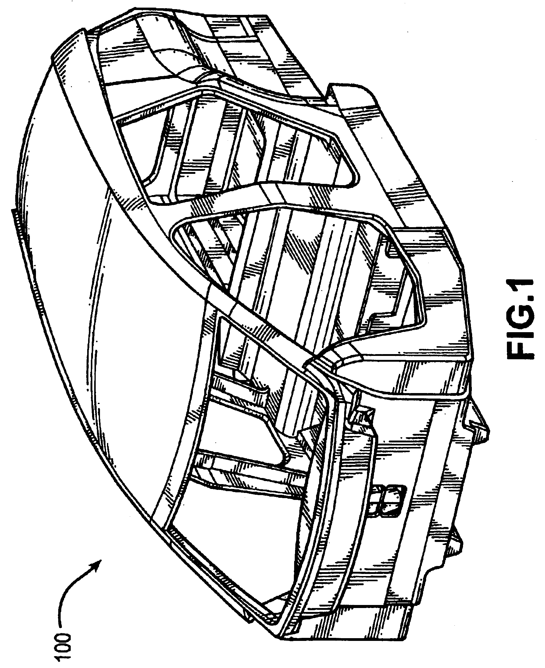
[0035]FIG. 1 shows an isometric view of a body structure 100 made in accordance with the present invention.

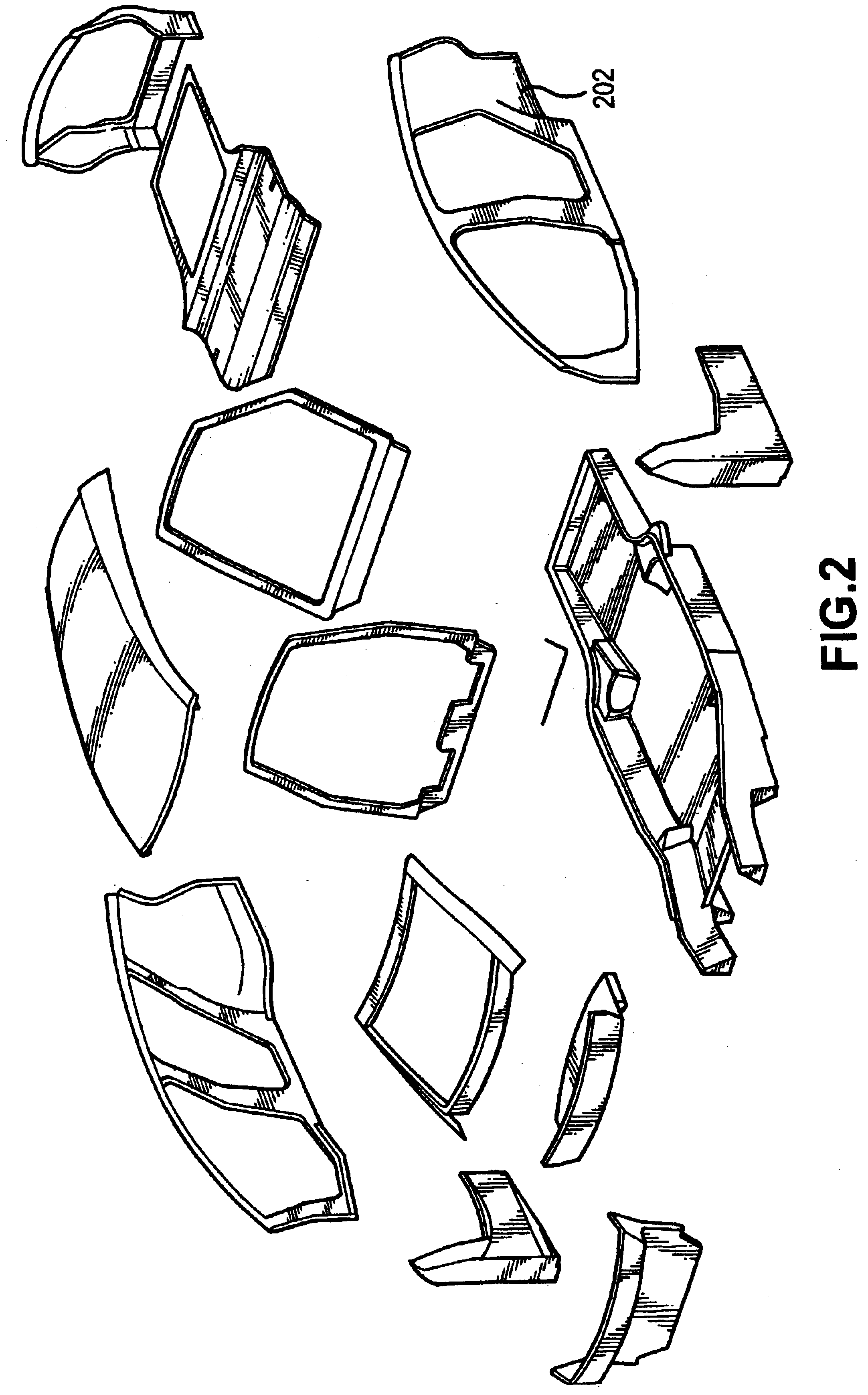
[0036]As shown in FIG. 2, the body structure is preferably divided into a number of parts. The boundaries of these parts are preferably selected to facilitate manufacture. One way to facilitate manufacture of the parts is to create parts that can be referred to as being “globally planar,” meaning that their overall shapes are as flat as possible. Complex overall geometries are achieved by combining more geometrically simple parts, as shown in FIG. 2. Such parts are more amenable to the process described herein because the blanks have to deform less to conform to the desired part shape. Globally planar parts also have simpler tooling.

[0037]All of the parts shown in FIG. 2 can be made according to the present invention. ...


PUM

PropertyMeasurementUnit
Angleaaaaaaaaaa
Speedaaaaaaaaaa
Displacementaaaaaaaaaa

Abstract

A process for continuous, tailored lamination of aligned composite materials in such a way that either pre-formed or pre-consolidated sheets are made available for subsequent infusion molding or stamping processes, the process comprising the steps of: material placement, consolidation / stabilization, cut and kit, fabrication, and final trim. A tailored blank machine is also described. The blank machine includes a series of material placement heads arranged in a linear or serial fashion along a single moving placement table, wherein each head lays down a single angle of the prescribed stacking sequence as the conveyer passes under the head at a constant speed wherein the angle is proportional to head traverse rate divided by conveyer speed.

Description

[0001]This is a continuation of U.S. patent application Ser. No. 09 / 916 / 254, filed Jul. 30, 2001, now U.S. Pat. No. 6,607,626, which claims benefit of 60 / 221,517, filed on Jul. 28, 2000.FIELD OF THE INVENTION[0002]The present invention addresses the affordable manufacture of advanced composite automotive structures using repeatable, monitorable, versatile, and production friendly approaches and processes.BACKGROUND[0003]The use of advanced composites, defined herein as highly aligned reinforcements of carbon, glass, or aramid fibers in a suitable polymer matrix of either thermoset or thermoplastic resins, is the focus of this invention. The specific intent to use aligned reinforcement is based on the following perception: The modulus of steel is 30,000,000 lbs / in2, whereas the modulus of aluminum is 10,000,000 lbs / in2. The modulus of a typical, higher quality glass epoxy prepreg is around 4,000,000 lbs / in2. While material stiffness can be compensated to some degree via the shaping o...

Claims


Application Information

Patent Timeline
IPC IPC(8): D04H1/42D04H3/00B29C70/06B29C70/38B29C70/46B29B11/16B29C70/48B29C70/50B29D99/00B29K105/08B32B5/12B32B37/00D04H13/00
CPCB29C70/228B29C70/38B29C70/386B29C70/46B29C70/48D04H1/42D04H3/00D04H13/002B29C70/50Y10T428/24124B29C70/545B29L2031/3055D04H3/04Y10T442/643Y10T442/644Y10T442/603B29C2793/0081B32B5/12
Inventor TAGGART, DAVID
Owner DIEFFENBACHER GMBH & CO KG
Learn More