
Interpolation synchronous detection method and radio communication system

a technology of interpolation synchronous detection and radio communication system, which is applied in the direction of error prevention, multi-path communication, digital transmission, etc., can solve the problems of difficult removal of interference influences, inability to remove interference influences due to multi-path transmission, and inability to perform interpolation synchronous detection. achieve the effect of improving the accuracy of demodulated data and minimizing transfer function errors

Inactive Publication Date: 2005-06-28
LENOVO INNOVATIONS LTD HONG KONG
View PDF9 Cites 11 Cited by
  • Summary
  • Abstract
  • Description
  • Claims
  • Application Information

AI Technical Summary

Benefits of technology

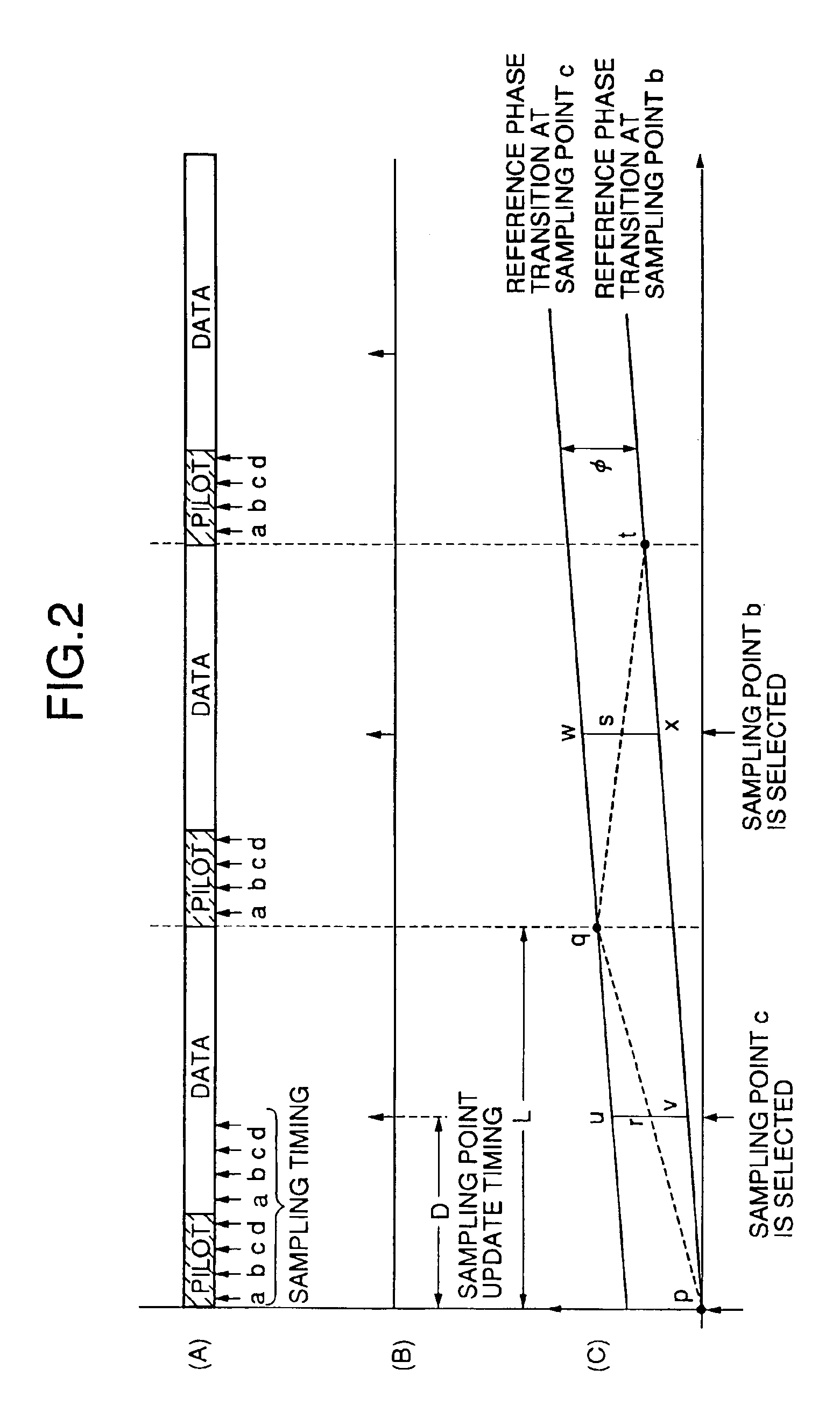
[0017]The present invention has been made in consideration of the above situation, and has as its object to provide an interpolation synchronous detection method which minimizes transfer function errors in a transmission path system by reducing the integral value of estimated reference phase errors in a transmission / reception section, thereby improving the accuracy of demodulated data, and a radio communication system which implements the method.
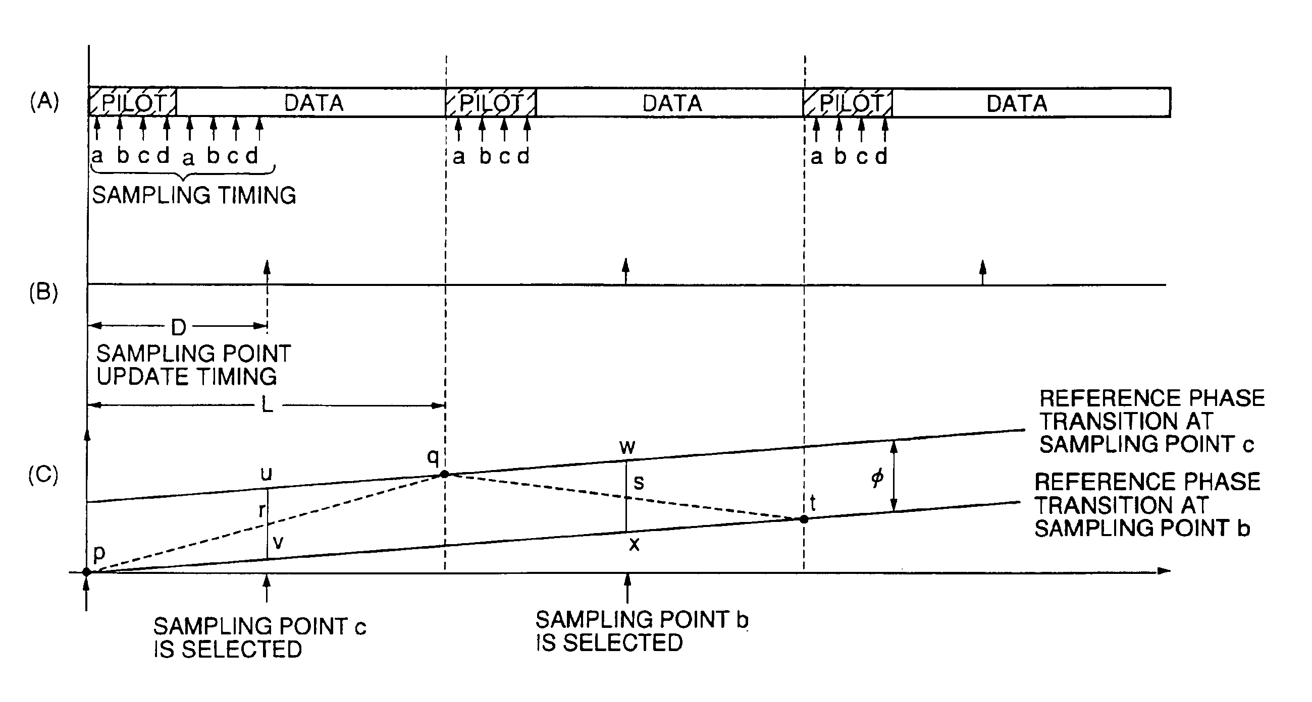
[0023]According to the present invention, when interpolation synchronous detection is to be performed by using pilot symbols, there is a correlation between an estimated reference phase error and a demodulation error. That is, the smaller the estimated reference phase error, the smaller the demodulation error. For this reason, synchronous detection of the information signal between pilot symbols is performed by linearly interpolating the transfer function estimated from the pilot symbols respectively located before and after the information signal, and the reception sampling point timing used for synchronous detection at a middle point between the pilot symbols respectively located before and after the information signal is updated, thereby minimizing the reproduced data error rate.

Problems solved by technology

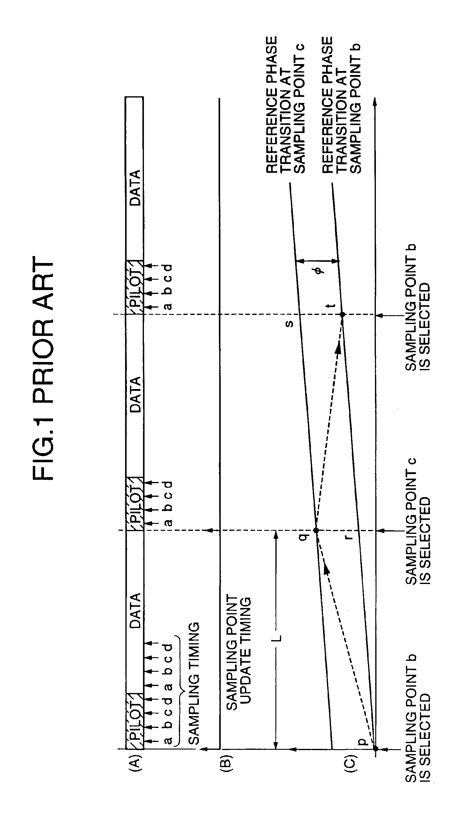
If, however, the multipath delay difference is smaller than ±1 chip which is the minimum difference allowing isolation of multipath influences by despreading, it is difficult to perform interpolation synchronous detection using known symbols for each despread symbol for the following reason.
In practice, multipath signals having a delay difference within ±1 chip are received on the receiving side with intersymbol interference, and it is generally difficult to remove the influences of the interference as in general radio communication schemes, other than the spread spectrum communication scheme, in which the influences of transmission path distortion due to multipath transmission cannot be removed.
In addition, since the influences of transmission paths at the respective reception sampling points can be regarded as independent, interpolation synchronous detection may not be properly performed.
Furthermore, in a radio communication system, the reception signal power dynamic range is generally very large.
This may make it impossible to perform normal interpolation synchronous detection as in the case described above in which despreading and interpolation synchronous detection are performed by selecting one optimal reception sampling point (e.g., a sampling point at which the eye pattern of a reception signal opens most) in predetermined cycles from the reception signals oversampled at n points.
Therefore, this area matches with an error component, and an error in a linearly interpolated estimated transfer function increases, resulting in a deterioration in the accuracy of demodulated data.

Method used


Image

  • Interpolation synchronous detection method and radio communication system
  • Interpolation synchronous detection method and radio communication system
  • Interpolation synchronous detection method and radio communication system

Examples


first embodiment

[0039]FIG. 3 shows the present invention. Referring to FIG. 3, a transmission section (not shown) modulates, at a transmission modulation stage, the data of a reception baseband signal 100 input to an A / D converter 10 which is to be transmitted according to a modulation scheme such as BPSK, QPSK, FSK, or QAM. The modulated signal is converted into an RF signal and power-amplified to be radiated from an antenna. The radiated transmission signal is received by the reception antenna of a mobile unit or base station through a plurality of spatial transmission paths. The received signal is then converted into a reception baseband signal by a reception section through an RF amplification stage, band-pass filter, mixer, IF amplification stage, and the baseband demodulation stage of a detection means. In this reception baseband signal 100, therefore, the transfer function becomes complicated through paths from the transmission modulation stage to the baseband demodulation stage according to...

second embodiment

[0044]FIG. 4 shows the arrangement of a reception section in a communication system according to the present invention. Referring to FIG. 4, a reception signal 190 received from an antenna is input to a radio section 70. A transmission section in a mobile unit or base station (not shown) modulates, at a transmission modulation stage, the data to be transmitted according to a modulation scheme such as BPSK, QPSK, FSK, or QAM. The modulated signal is converted into an RF signal, power-amplified, and radiated from the antenna. The radiated transmission signal is received by the reception antenna of a mobile unit or base station through a plurality of spatial transmission paths. As a consequence, the reception signal 190 is obtained. The radio section 70 includes an RF amplification stage, band-pass filter, local oscillator, frequency conversion mixer, IF amplification stage, and baseband demodulation stage as a detection means. The output from the baseband demodulation is the reception...


PUM


Abstract

In an interpolation synchronous detection method in a radio communication system in which a pilot symbol whose phase point is known is periodically inserted in an information signal to allow interpolation synchronous detection on a receiving side, synchronous detection of the information between the pilot symbols is performed by linearly interpolating a transfer function estimated from the pilot symbols respectively located before and after the information signal, and a reception sampling point timing used for the synchronous detection is updated at the middle point between the pilot symbols respectively located before and after the information signal. A radio communication system is also disclosed.

Description

BACKGROUND OF THE INVENTION[0001]1. Field of the Invention[0002]The present invention relates to a pilot interpolation synchronous detection method for a transmission circuit in a radio communication system and, more particularly, to an interpolation synchronous detection method and radio communication system which can be used for, for example, a pilot interpolation synchronous detection spread spectrum scheme.[0003]2. Description of the Prior Art[0004]Recently, a pilot interpolation synchronous detection spread spectrum scheme has been proposed as one of the mobile communication schemes in RCS 94-98 “Characteristics of Interpolation Synchronous Detection RAKE in DS-CDMA” by ARIB (Association of Radio Industries and Businesses).[0005]In pilot interpolation synchronous detection, first and second pilot signals whose phase points are known are cyclically or periodically inserted in an information signal to form a frame, and a transmission path that varies due to multipath Rayleigh fad...

Claims


Application Information

Patent Timeline
Patent Type & Authority Patents(United States)
IPC IPC(8): H04B1/707H04L7/02H04B1/7073H04L1/00H04B1/76H04B7/005H04J13/00
CPCH04B1/7073H04B1/7117H04B1/7115H04B1/7075
Inventor TSUMURA, SOICHI
Owner LENOVO INNOVATIONS LTD HONG KONG
Learn More