
Integrated micromachine relay for automated test equipment applications

a micromachine relay and test equipment technology, applied in the field of test equipment, can solve the problems of electronic switches having low bandwidth or high resistance when placed on electronic switches, needing more complex control circuits, etc., and achieve the effect of reducing the electric length

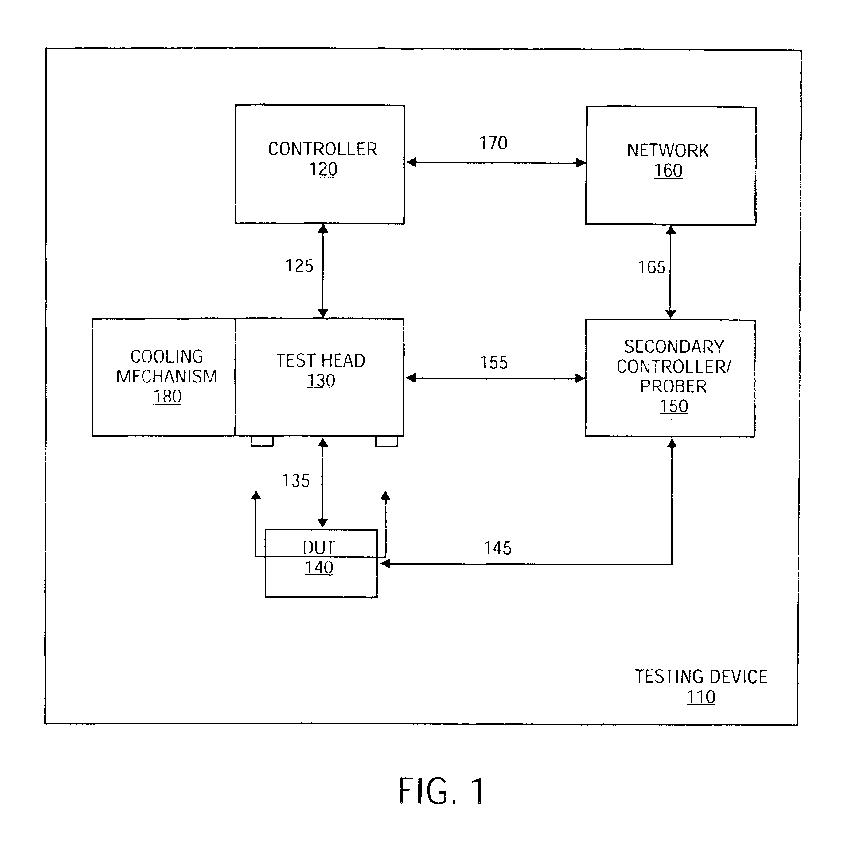
Inactive Publication Date: 2005-06-07
LTX CORP
View PDF30 Cites 5 Cited by
  • Summary
  • Abstract
  • Description
  • Claims
  • Application Information

AI Technical Summary

Benefits of technology

[0007]It is a further object of this invention to reduce the electric length from the device under test (DUT) to the pin electronics.

Problems solved by technology

Reducing the size of the relays may result in the need for more complex control circuits.
However, the size of the components that may be placed on a test head is limited.
However, electronic switches either have low bandwidth or high resistance when they are on, or low breakdown voltage and when they are off.
Transistors are disadvantageous, as they combination of through bandwidth, on resistance, and

Method used


Image

  • Integrated micromachine relay for automated test equipment applications
  • Integrated micromachine relay for automated test equipment applications
  • Integrated micromachine relay for automated test equipment applications

Examples


Embodiment Construction

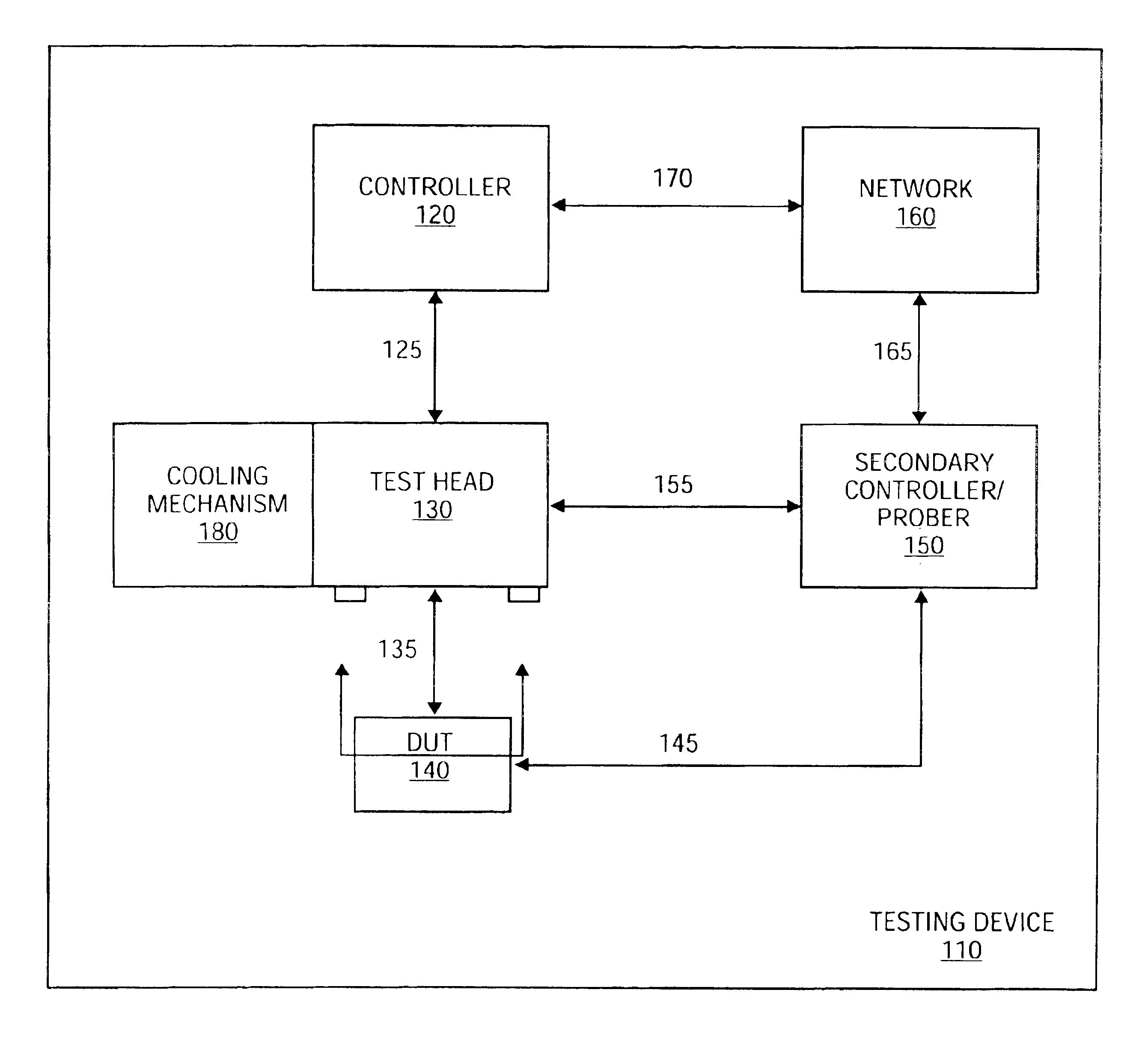
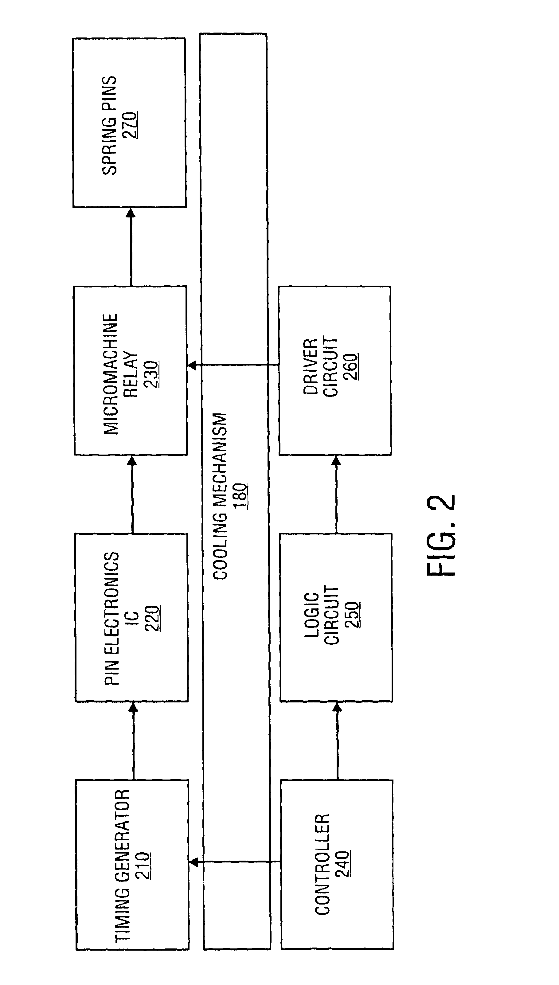
[0029]A method and apparatus for using a micromachine relay in an automated test system is described. Using a micromachine relay in automated testing equipment reduces an electrical length between the pin electronics and the device under test (DUT). The micromachine relay could further be integrated onto the pin electronics integrated circuit (IC). The features of this design include a shorter electrical length between the device under test (DUT) and the pin electronics, increased bandwidth, and higher pin count by reducing associated control sizing.

[0030]Using micromachined relays further provides a lower fabrication cost. Furthermore, the pin electronics device may be mounted directly below the spring pin ring, since the reduction in size provides additional space. The use of micromachine relays also permits use of the system for mixed signal testing. Furthermore, because the pin electronics are dose to the center, there is a shorter electrical length, leading to better signals. H...


PUM


Abstract

A method and apparatus for a micromachine relay is provided. A pin controller comprises at least one spring pin designed to movably couple the pin controller to a device under test (DUT) to provide signals to the DUT. The pin controller further includes a micromachine relay coupled to the at least one spring pin to control the movement of the at least one spring pin and an integrated circuit for controlling the micromachine relay.

Description

[0001]The present application claims priority from and is a divisional application of U.S. patent application Ser. No. 09 / 859,842, filed May 16, 2001, now U.S. Pat. No. 6,700,396, which is owned by the same assignee as the present patent application.FIELD OF THE INVENTION[0002]The present invention relates to test equipment, and more specifically, to relays used in test equipment.BACKGROUND[0003]Electronic devices are often tested using automatic test equipment (ATE). Generally, the tester includes a computer system that coordinates and runs the tests, and a testing apparatus. The testing apparatus includes a test head, into which the device under test (DUT) is placed.[0004]Contacts in the test head are used to couple the trace of the DUT to the control mechanisms. These contacts, generally spring pins, are designed to send through a high fidelity and high speed signal from the computer system. A control circuit and timing generation generally controls access. Pin electronics are el...

Claims


Application Information

Patent Timeline
Patent Type & Authority Patents(United States)
IPC IPC(8): G01R1/073
CPCG01R1/07314
Inventor SMITH, STEPHEN W.CREEK, WILLIAM R.
Owner LTX CORP
Learn More