Charged particle beam irradiation equipment having scanning electromagnet power supplies
a chargeable particle and power supply technology, applied in the field of chargeable particle beam irradiation equipment, can solve the problems of delayed output voltage generation, burden and inconvenience of patients, and difficulty in uniformizing the irradiation dose at the affected part, so as to reduce the irradiation time of the charged particle beam in the irradiation object, the effect of short time and short tim
- Summary
- Abstract
- Description
- Claims
- Application Information
AI Technical Summary
Benefits of technology
Problems solved by technology
Method used
Image
Examples
embodiment 1
(Embodiment 1)
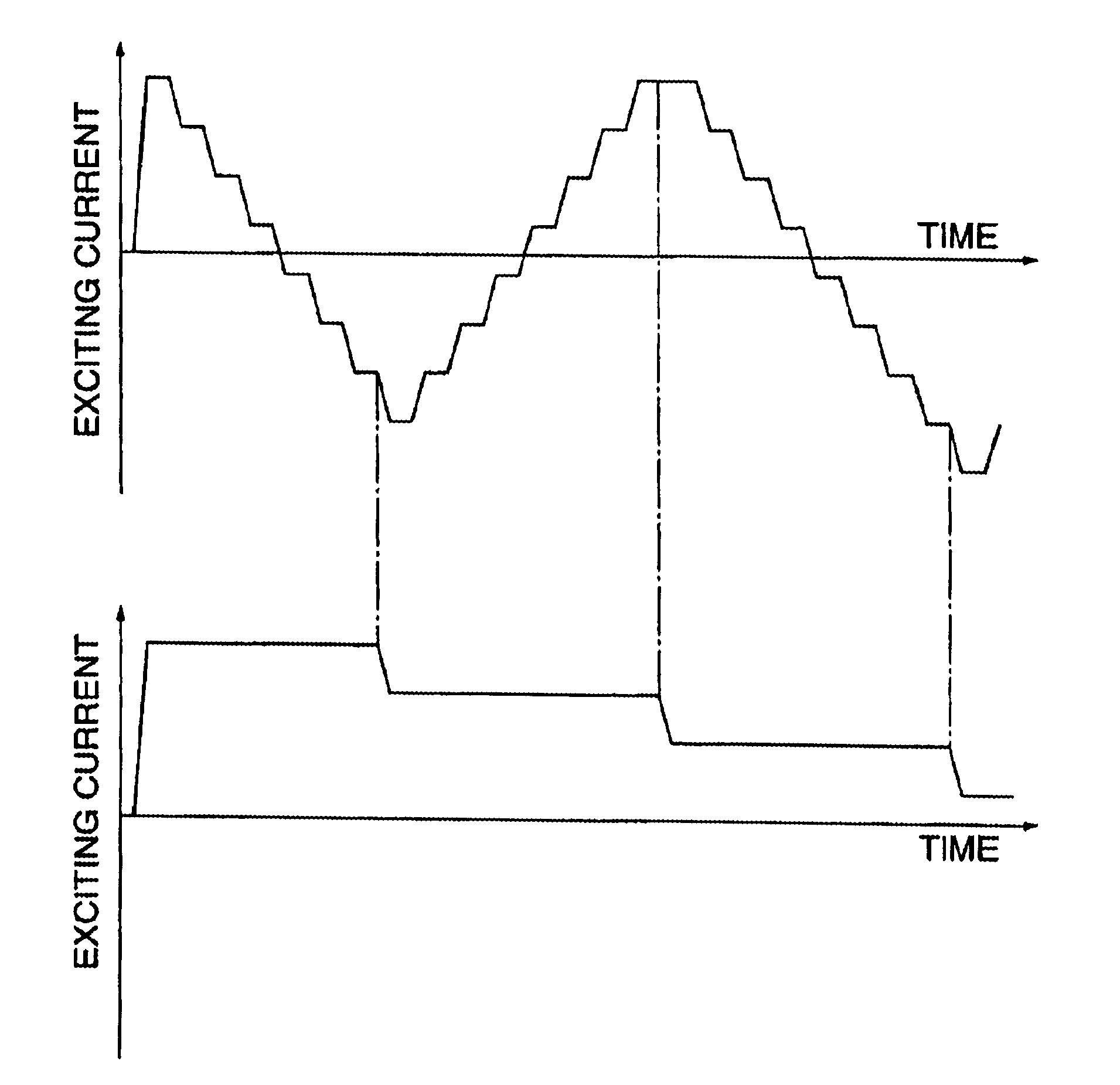
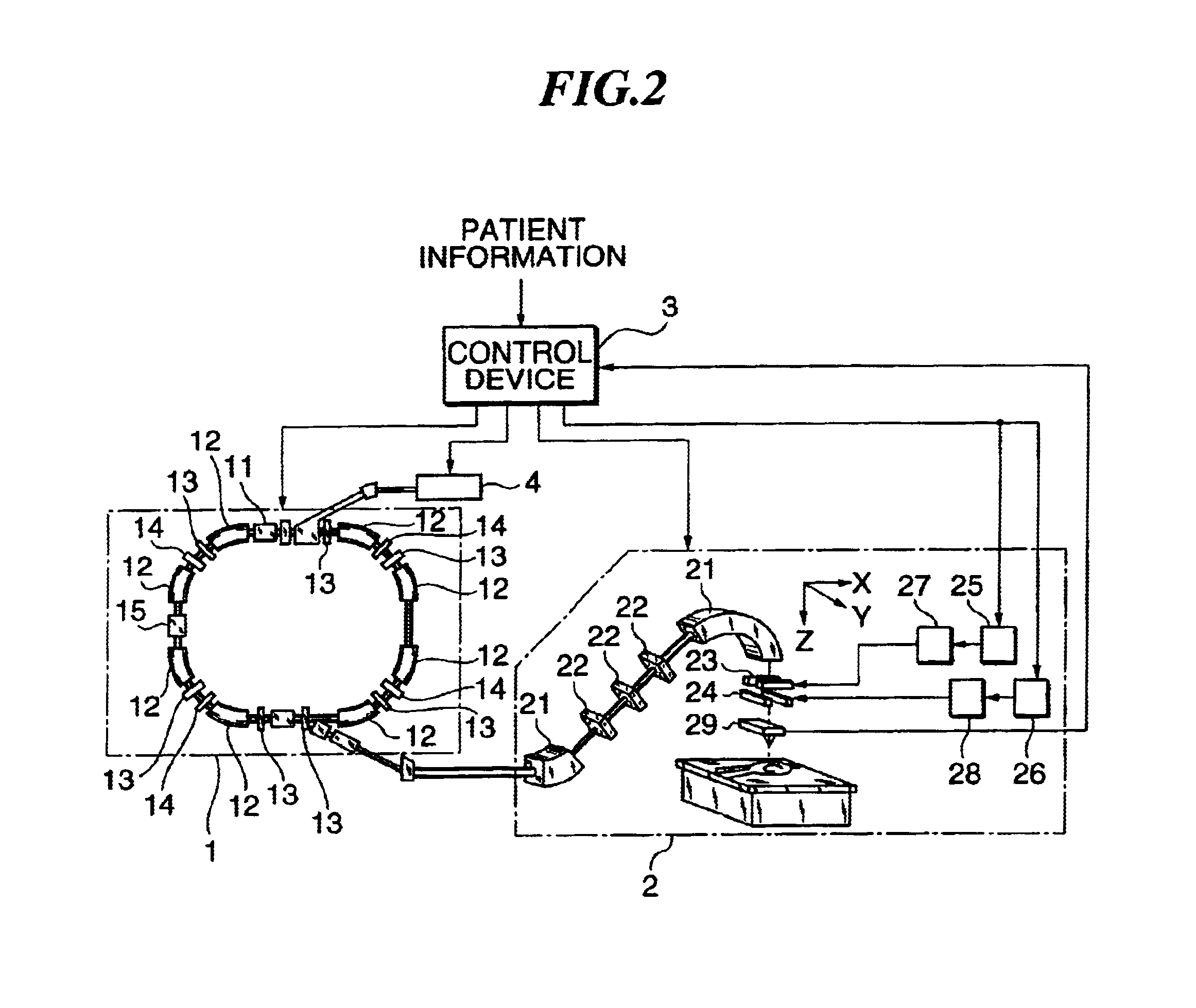
[0019]FIG. 2 shows the charged particle beam irradiation equipment of the preferred embodiment according to the present invention. By the way, the charged particle beam irradiation equipment of FIG. 2 is equipment for performing cancer treatment by applying a charged particle beam accelerated by a synchrotron 1 to the affected part of a cancer patient with a rotational irradiation device 2. Further, the charged particle beam irradiation equipment according to the present embodiment, as shown in FIG. 3, divides the affected part into a plurality of layered areas L1-L9 in a direction of beam propagation, and each layered area is further divided into a plurality of irradiation areas A11, A12, . . . , to each of which the beam is applied.
[0020]In the cancer treatment by means of the charged particle beam irradiation equipment of FIG. 2, first patient information such as the depth position of the affected part, the shape of the affected part, irradiation dose to be achieved...
embodiment 2
(Embodiment 2)
[0061]Referring to FIG. 7, the charged particle beam irradiation equipment, namely another embodiment of the present invention, will be described. The charged particle beam irradiation equipment according to this embodiment is different from the Embodiment 1 mainly in the configuration of the scanning electromagnet power supply. In the following described is different points from Embodiment 1.
[0062]FIG. 7 shows a configuration of a scanning electromagnet power supply 27 according to the present embodiment. By the way, a scanning electromagnet power supply 28 has a similar configuration; therefore its explanation is omitted. Further, a total block diagram of the present embodiment is the same as Embodiment 1, as in FIG. 2.
[0063]In the FIG. 7, the power supply unit 27a has a voltage detector 278a, and the voltage detector 278a detects the output voltage of the inverter 273a, namely the output voltage of the power supply unit 27a. A voltage detected value detected by the ...
PUM
 Abstract
Description
Claims
Application Information
 - R&D
- Intellectual Property
- Life Sciences
- Materials
- Tech Scout
- Unparalleled Data Quality
- Higher Quality Content
- 60% Fewer Hallucinations
Browse by: Latest US Patents, China's latest patents, Technical Efficacy Thesaurus, Application Domain, Technology Topic, Popular Technical Reports.
© 2025 PatSnap. All rights reserved.Legal|Privacy policy|Modern Slavery Act Transparency Statement|Sitemap|About US| Contact US: help@patsnap.com


