
Printing plate processing apparatus

a technology of processing apparatus and printing plate, which is applied in the direction of printers, instruments, photosensitive materials, etc., can solve the problems of deteriorating the ability of silicate materials or binder materials to dissolve, generating hard to dissolve crystallized materials, and increasing the amount of crystallized materials

Inactive Publication Date: 2005-06-07
FUJIFILM CORP +1
View PDF4 Cites 0 Cited by
  • Summary
  • Abstract
  • Description
  • Claims
  • Application Information

AI Technical Summary

Benefits of technology

[0017]In view of the above-described circumstances, the present invention provides a printing plate processing apparatus which prevents, without effecting a roller washing operation or an operation using a cleaning plate, deterioration in the finished quality of a printing plate, which results from that attached material, which is produced due to a developing solution adhering to a peripheral surface of a roller and coming into contact with carbon dioxide in the air, being transferred to the surface of the printing plate.
[0023]For this reason, by setting the amount of time for cleaning during which the conveying roller pair is driven to rotate in accordance with the operation stoppage time of the apparatus, crystallized material can be efficiently and reliably removed from the peripheral surface of the conveying roller pair. Further, it is possible to reliably prevent the crystallized material from adhering to a printing plate to be processed first and having an adverse effect on the finished quality of a printing plate surface or the printing performance.
[0027]For this reason, the concentration of carbon dioxide in the working environment is detected by the detector, and the conveying roller pair is driven to rotate for the amount of time set based on the concentration of carbon dioxide and the stoppage time of the apparatus. As a result, crystallized material generated on the peripheral surfaces of the rollers can be removed more efficiently and reliably.
[0032]Moreover, the driving time of the pair of conveying rollers is set so as to increase as a concentration of carbon dioxide in the environment in which the apparatus is installed becomes higher.

Problems solved by technology

Due to the component coming into contact with carbon dioxide, the ability thereof for dissolving silicate material or binder material deteriorates.
As a result, silicate material or binder material causes generation of crystallized material which is hard to dissolve.
Further, the crystallized material increases as the amount of time that the developing solution comes into contact with carbon dioxide becomes longer.
However, in a case in which the rollers are merely driven to rotate intermittently, it is necessary to drive the rollers intermittently even when the operation of the apparatus stops.
Further, in a case in which provision of a roller washing step in addition to a washing step by rollers is supposed, the structure of the developing step becomes complicated, and a developing solution in a developing tank is apt to come in contact with carbon dioxide in the air.
Moreover, in a case in which the rollers are washed, the developing solution may be diluted due to the washing water.
Accordingly, ordinarily, when the operation of a PS plate processor is started, a complicated operation is carried out in which a cleaning plate is inserted prior to insertion of a PS plate, and attached material adhering to the peripheral surface of a roller disposed outside the processing solution is transferred to the cleaning plate, or the like.

Method used


Image

  • Printing plate processing apparatus
  • Printing plate processing apparatus
  • Printing plate processing apparatus

Examples


first embodiment

[First Embodiment]

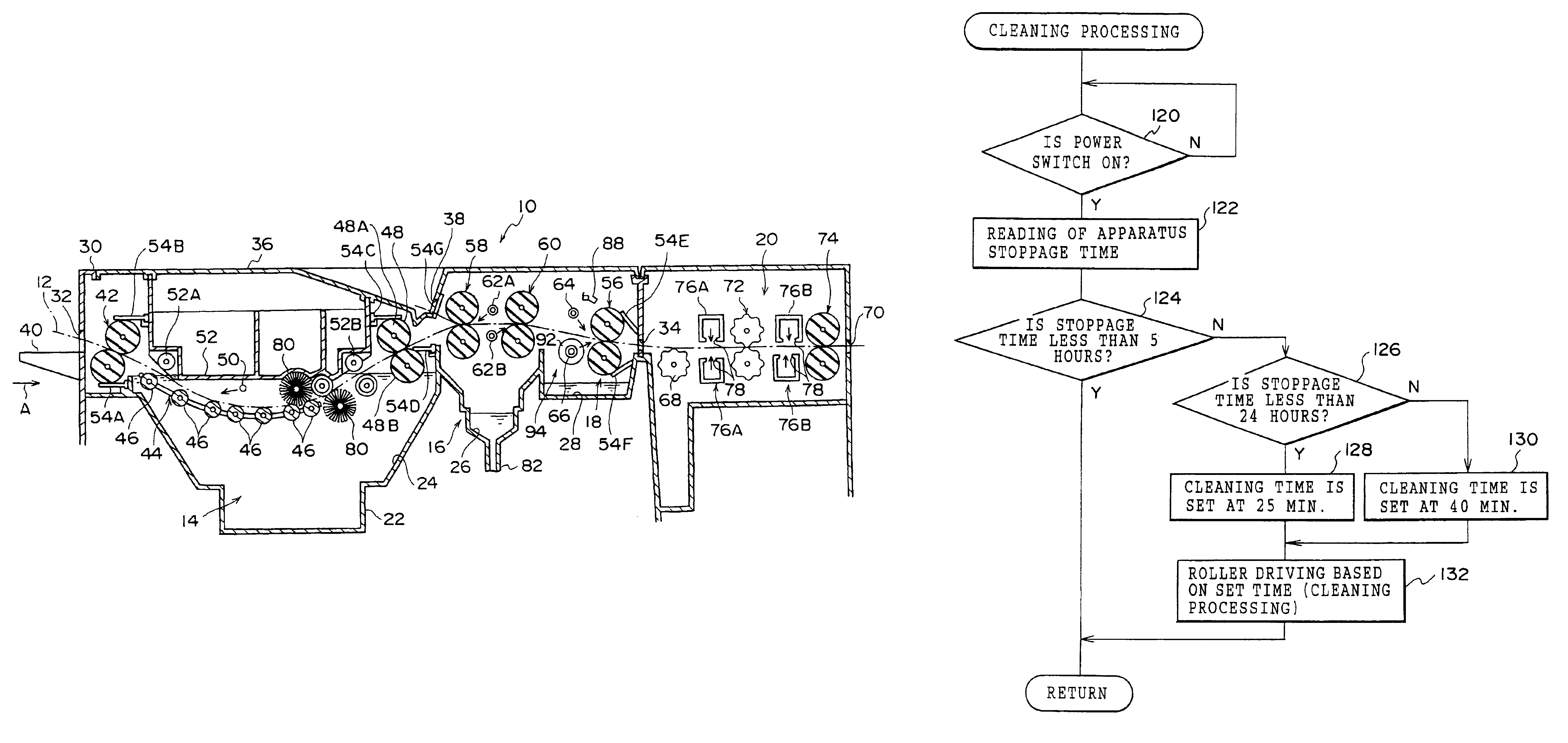
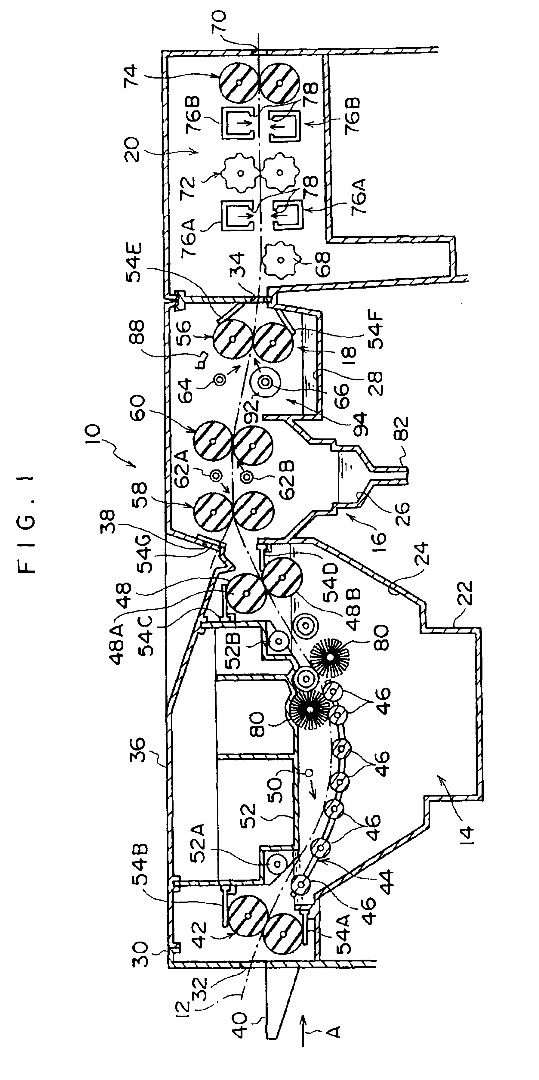
[0039]An embodiment of the present invention will be described hereinafter with reference to the attached drawings. In FIG. 1, the structure of a printing plate developing apparatus (hereinafter referred to as a “PS plate processor 10”) applied as an example of a processing plate processing apparatus is schematically shown. In the PS plate processor 10, developing processing for a photosensitive planographic printing plate (hereinafter referred to as a “PS plate 12”) such as a photo-polymer plate which has undergone image exposure using an exposure device (not shown) is carried out.

[0040]The PS plate 12 is structured in such a manner that a photosensitive layer is formed on a substrate which is a thin-walled rectangular flat plate (for example, an aluminum substrate). A photo-polymer plate comprises photosensitive layers including a photo adhesion layer, a photo polymerization layer, and an overcoat layer superposed on one another, and polymerization reaction in an...

second embodiment

[Second Embodiment]

[0107]Next, a second embodiment of the present invention will be described. Note that a basic structure of the second embodiment is the same as that of the aforementioned first embodiment, and the same members as those of the first embodiment will be denoted by the same reference numerals, and a description thereof will be omitted.

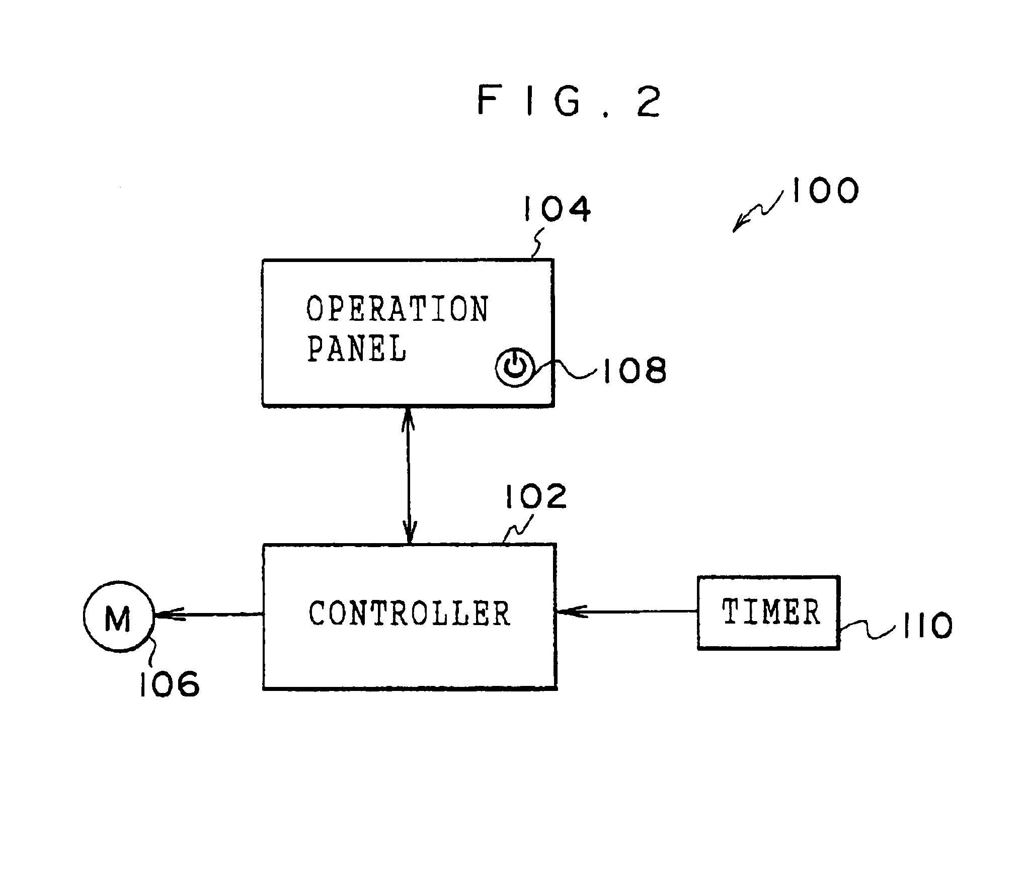
[0108]In FIG. 4, the structure of a control section 100A according to the second embodiment of the present invention is schematically shown. In the control section 100A, a carbon dioxide detecting sensor 150 for detecting carbon dioxide in an environment in which the PS plate processor 10 is installed is provided. The carbon dioxide detecting sensor 150 is connected to a controller 102A.

[0109]The controller 102A is provided so as to set the cleaning time of the conveying roller pair 48 (that is, the operating time of the conveying motor 106) based on the operation stoppage time of the processor measured by the timer 110 and the concentra...


PUM


Abstract

A printing plate processing apparatus provides a step in which a printing plate which has undergone image exposure is processed by being immersed in a developing solution, and the printing plate is delivered while the developing solution is being squeezed out from the printing plate by a conveying roller pair which is partially immersed in the developing solution. A stoppage time of the apparatus is measured, and the conveying roller pair is driven to rotate for an amount of time set in accordance with a measured result of the stoppage time when operation of the apparatus is started, thereby allowing the conveying rollers to be cleaned. A concentration of carbon dioxide in an environment in which the apparatus is installed is detected, and based on the detected result and the measured result of the apparatus stoppage time, the driving time of the conveying roller pair is set.

Description

CROSS REFERENCE TO RELATED APPLICATION[0001]This application claims priority under 35 USC 119 from Japanese Patent Application No.2002-288001, the disclosure of which is incorporated by reference herein.BACKGROUND OF THE INVENTION[0002]1. Field of the Invention[0003]The present invention relates to a printing plate processing apparatus in which a photosensitive planographic printing plate is processed with processing solutions.[0004]2. Description of the Related Art[0005]As a photosensitive material, photosensitive planographic printing plates (hereinafter referred to as “PS plates”) comprising a photosensitive layer formed on an aluminum substrate or the like is used. In a PS plate processor which is a photosensitive material processing apparatus (printing plate processing apparatus) in which PS plates are processed, a plurality of processing steps which use processing solutions are provided: a developing step in which the PS plate is processed by being immersed in a developing sol...

Claims


Application Information

Patent Timeline
IPC IPC(8): G03F7/30G03D5/00G03D5/04G03F7/00
CPCG03F7/3064G03D5/04
Inventor NOZAWA, RYOEIIWAMOTO, TAKAYUKIKIMURA, AKINORI
Owner FUJIFILM CORP
Learn More