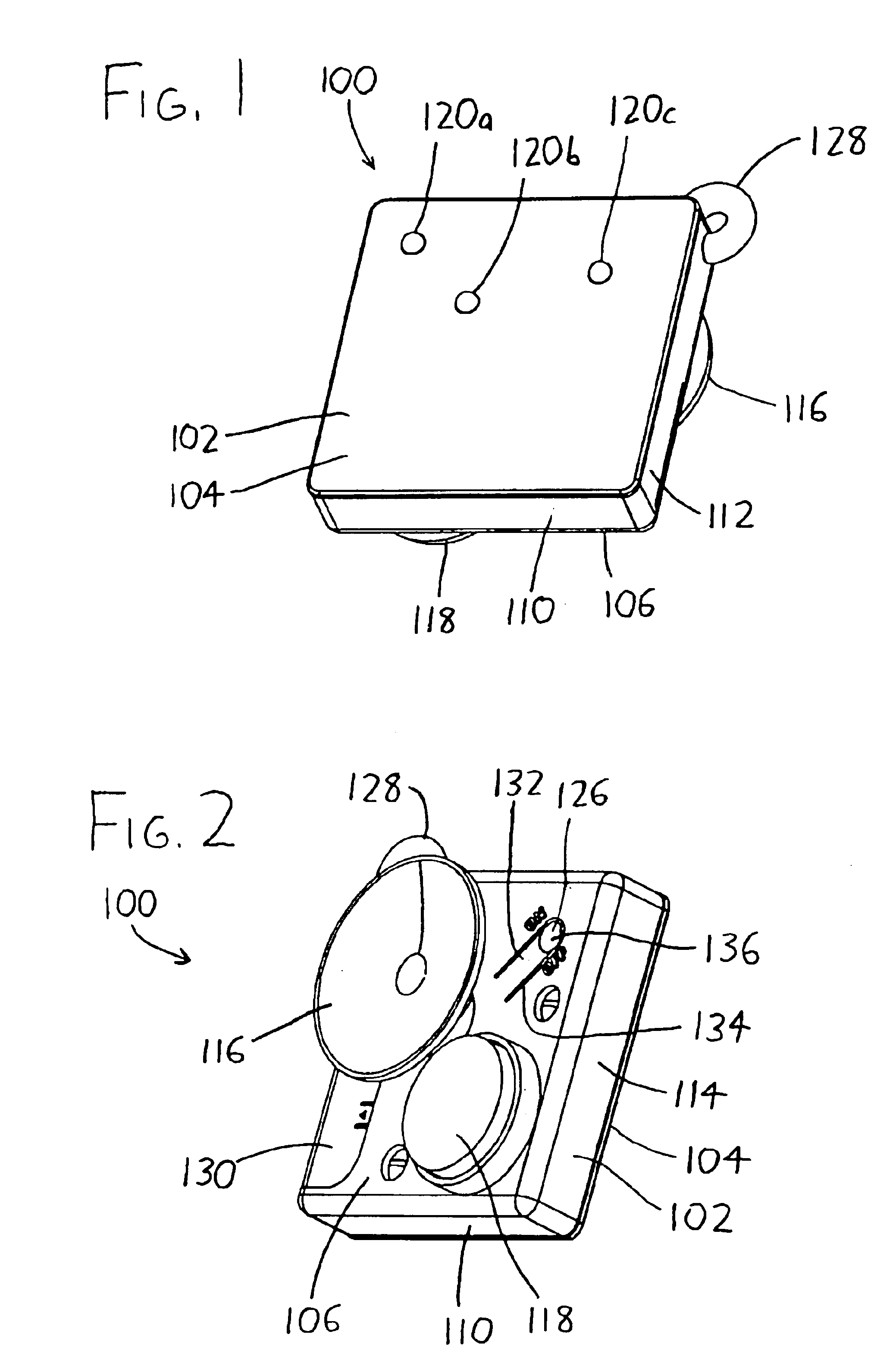
[0016]Two or more (and preferably three or more) light-emitting diodes (LEDs) 120a, 120b, and 120c (collectively referred to herein as LEDs 120) are then spaced about the front face 104 of the casing 102 to provide a
light signal to delivery or emergency personnel when the signal light 100 is placed outside a
service location. As will be discussed at greater length below, suitable LEDs 120 provide extremely high light output—potentially visible over a
mile away—with extremely low power draw, thereby diminishing concerns regarding battery and light consumption and replacement. At least some of the LEDs 120 are preferably substantially spaced apart across the front face 104 of the casing 102, e.g., by a distance at least as great as approximately one-half of the greater of the width or height dimensions of the casing 102. With this spacing, owing to the brightness of LEDs, the spaced LEDs 120 will still appear as individual
point light sources when viewed from standard road-to-
residence distances. This helps a viewer differentiate the signal light 100 from a standard residential, business, or vehicle light since it appears as a distinctive set of closely-spaced point sources of light. When viewed at greater distances, the LEDs 120 may “blend” and appear as a single
light source, but as discussed below, by making at least one of the LEDs 120 flash, the light of the flashing LED will add to (and then subtract from) any other light transmitted from the signal light 100, thereby also helping a viewer distinguish the signal light 100 from other common light sources.
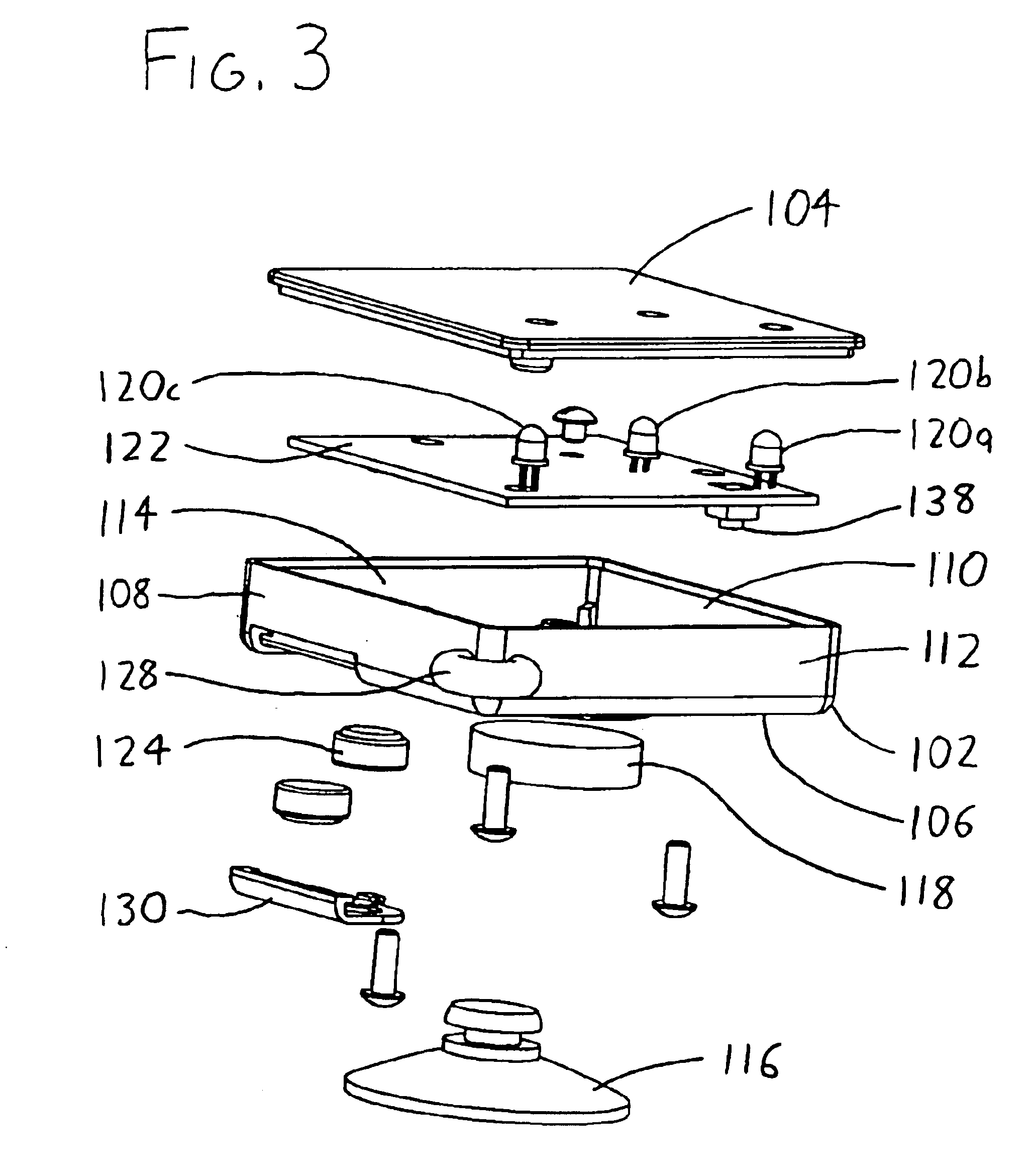
[0017]The LEDs 120 are powered by a powering circuit (depicted as a circuit board 122 in FIG. 3) which supplies the LEDs 120 with power from one or more batteries 124 (FIG. 3) when a switch 126 (FIG. 2) is actuated. The powering circuit 122 preferably causes at least one of the LEDs 120 to be illuminated at a frequency of greater than 0.5 Hz when the switch 126 is actuated, with the flashing of the LED(s) thereby helping a viewer better distinguish the signal light 100 from other “static” ambient nonflashing lights (e.g., a common house light). The distinctiveness of the emitted light is believed to be enhanced where three or more LEDs 120 are used on the signal light 100, and wherein at least one of the LEDs 120 does not rest along a line defined by two of the other LEDs 120 (i.e., the LEDs 120 are not all oriented along a straight line, and are “scattered” to some degree). When the LEDs 120 are arrayed in this fashion with at least one of them flashing, the signal light 100 emits a distinctive light pattern at standard road-to-residence distances which does not appear as a unitary light (in contrast to the situation where all lights are statically lit along a straight-
line array); rather, a cluster of point fight sources is seen, with at least one of them flashing, a pattern which is uncommon in commonly encountered lights such as residential / business lights, vehicle lights, and the like. The emitted light becomes even more distinctive where two or more of the LEDs 120 are lit at different times (for example, where the LEDs 120 shown in FIG. 1 are sequentially flashed in
clockwise order). When this is done, it is possible to distinguish between different LEDs 120, and different flash patterns, at standard road-to-residence distances. Stated differently, as an example, if the LEDs 120 shown in FIG. 1 are sequentially flashed in
clockwise order, they will appear (at standard road-to-residence distances) as separate spaced lights rather than as one single light: since LEDs 120 have great brightness, one can tell when one LED is turned off and an adjacent LED is turned on even at significant distances. Even when one LED is turned on at the same time as an adjacent LED, they do not “blur together” to a viewer because the additive / subtractive effect on light output when one LED is turned on or off allows a viewer to tell that more than one LED is present.
[0018]The foregoing feature beneficially allows the signal light 100 to effectively send a distinctive signal to a distinct delivery company or emergency service—for example, the signal light 100 can be configured to have the LEDs 120 flash sequentially
clockwise for a certain pizza delivery company, or to have the LED 120a stay on constantly while LEDs 120b and 120c sequentially flash for a certain video / entertainment media delivery company, or to have LEDS 120a and 120b first simultaneously illuminate followed by simultaneous illumination of LEDs 120b and 120c for a certain paramedic service, etc. Since each of these unique illumination “signatures” may be differentiated by an observer at standard road-to-residence distances, and since each different delivery / emergency concern can be trained to recognize its own distinct illumination signature, the signal light 100 can serve to indicate to a particular concern that service is expected at the location where the signal light 100 is viewed, even if there is significant surrounding “
noise” from ambient residential, business, and vehicle lights. Further, even if multiple addresses along the same street each use the signal light 100—for example, if one residence uses the signal light 100 to signal to one pizza delivery company that a pizza is expected, and another residence uses the signal light 100 to signal to another pizza delivery company that its pizza is expected—the delivery companies will not be misdirected to the wrong address since they can each recognize the unique illumination signature chosen by that company.
[0019]The signal light 100 provides an especially inexpensive, convenient, and effective means for service providers to allow their consumers to contact them for service, and then signal to the providers where the service is to be made. Since the signal light 100 can be inexpensively manufactured, a
service provider may provide the signal light 100 to its consumers at low or no cost. The front face 104 of the casing 102 may provide a fairly significant area upon which indicia may be printed—again note FIG. 1, which shows an exemplary signal light 100 at or near the size at which the signal light 100 may actually be provided—and thus the front face 104 may bear the name and
telephone number of a particular service (for example, “ALEX'S PIZZA” followed by a phone number). A
consumer may therefore (for example) look to the signal light 100 when mounted on a refrigerator, make a service call, and then place the signal light 100 on or adjacent to the
consumer's door to allow the service's personnel to more rapidly identify the
delivery location and effect delivery. Since the
unit cost of the signal light 100 can increase if each
service provider must have an individually-designed powering circuit 122 providing that concern's own individual illumination pattern or “signature,” the powering circuit 122 for the signal light 100 preferably includes reconfiguration means allowing the illumination pattern of the LEDs 120 to be individually programmed for an individual
service provider, whereby the reconfiguration means can be easily reconfigured to provide one unique illumination signature for one service provider and another unique illumination signature for another service provider, while both providers still use essentially the same signal light structure. This is most preferably done by including a
chip (e.g., a
microcontroller) with an
electronic memory onto which the illumination instructions for the LEDs 120 can be loaded. Thus, the manufacturer of the signal light 100 may readily format it with a unique illumination signature for each different service provider by simply loading the desired signature for that service provider into the memory provided on the powering circuit 122.
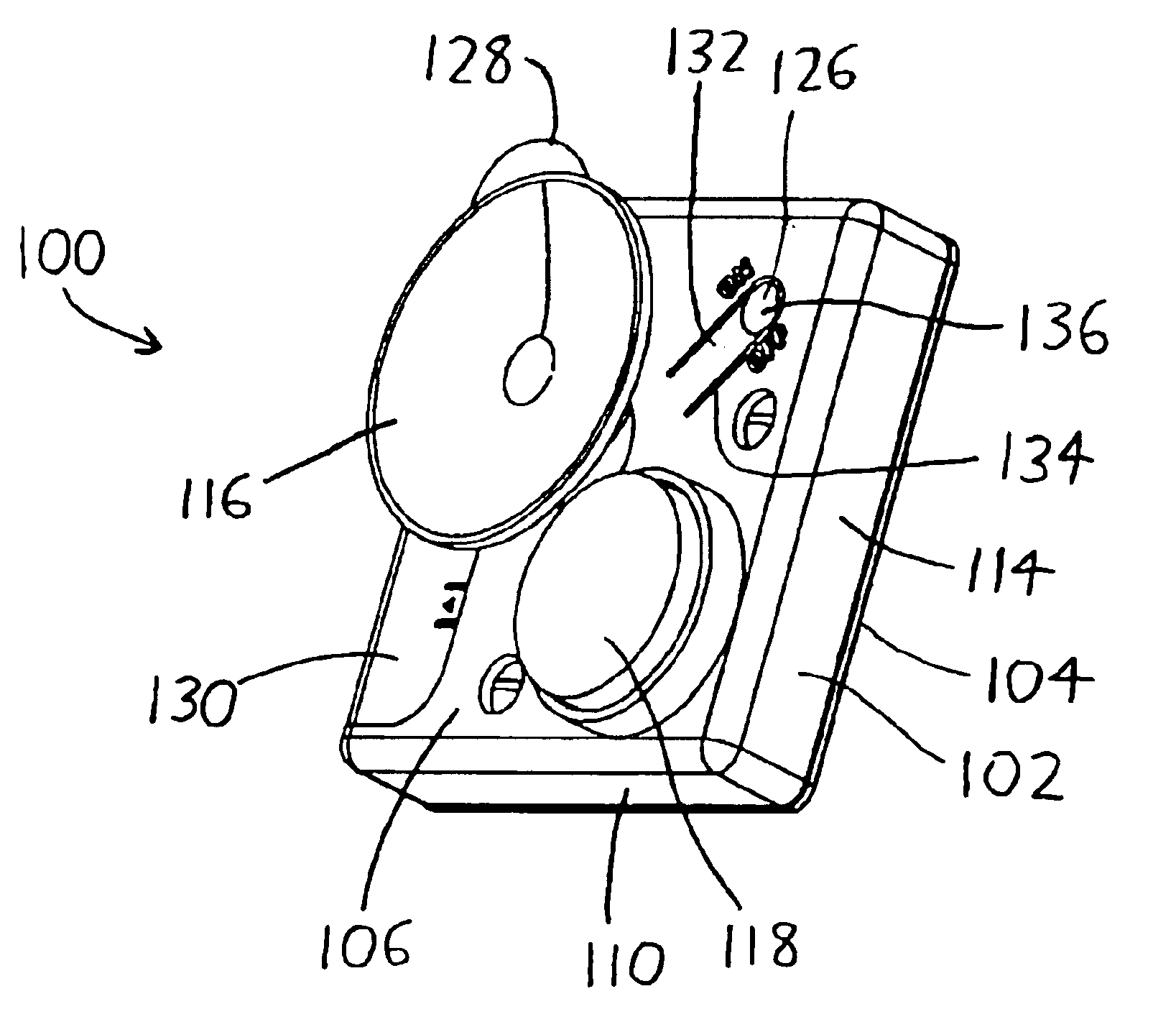
[0020]As previously noted, the signal light 100 is preferably easily mountable on a common vertical household surface such as a refrigerator door, and it is also preferably easily mountable to a window or door on the exterior of a
delivery location. A particularly preferred mounting arrangement is best seen in FIG. 2, wherein it is seen that the rear face 106 of the casing 102 includes both a
magnet 118 and a suction cup 116. The suction cup 116 is flexible, and it protrudes outwardly from the casing 102 past the
magnet 118. As a result, the suction cup 116 may be pressed against a surface to engage the surface, provided it is a smooth and nonporous surface. Such compression of the suction cup 116 brings the magnet 118 into close proximity with the surface, and thereby allows the signal light 100 to cling to a magnetic surface even if the suction cup 116 win not do so. Such an arrangement allows the signal light 100 to firmly
mount to a refrigerator, since the exteriors of most refrigerators are both smooth and magnetic, whereby both the magnet 118 and suction cup 116 will hold the signal light 100 to the refrigerator. However, the signal light 100 also preferably bears a lanyard 128 from which a hanging loop / strap may extend (if desired), allowing a hanging loop to be used where the signal light 100 is to be mounted at locations where no smooth and / or magnetic surfaces are available (e.g., allowing the signal light 100 to be hung about the
door handle of a rough wooden door).
