
Method of depositing DLC on substrate

a technology of dlc and substrate, which is applied in the field of ion beam depositing techniques, can solve the problems of premature breakdown of the layer, reduced longevity, and more susceptible to breakage of the c bond in the dlc layer, so as to improve the longevity and/or longevity reduce the ion mixing at the bottom and improve the longevity and/or durability of the dlc layer

Inactive Publication Date: 2005-04-12
GUARDIAN GLASS LLC
View PDF20 Cites 26 Cited by
  • Summary
  • Abstract
  • Description
  • Claims
  • Application Information

AI Technical Summary

Benefits of technology

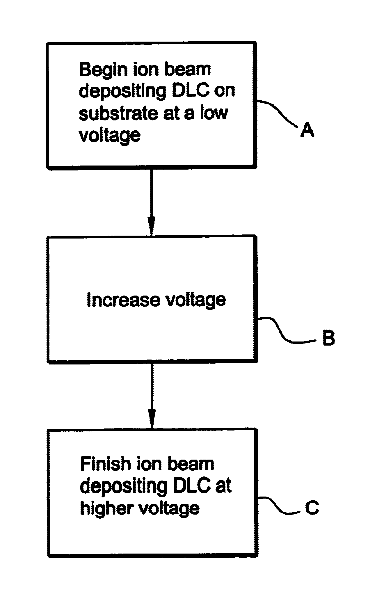
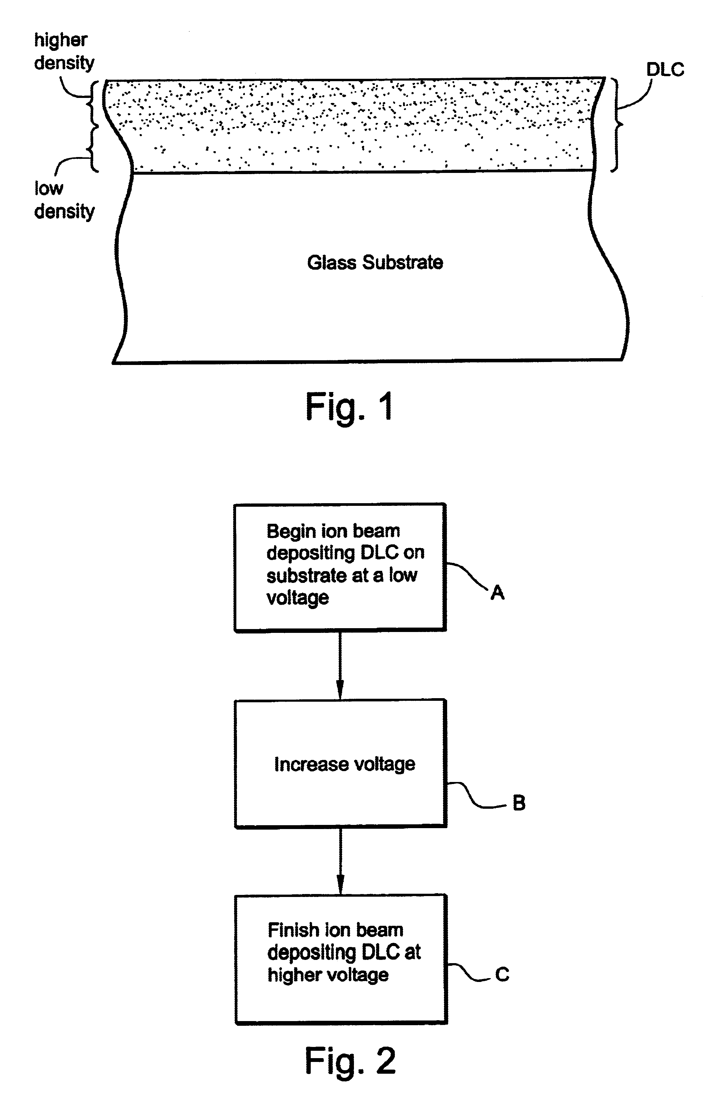
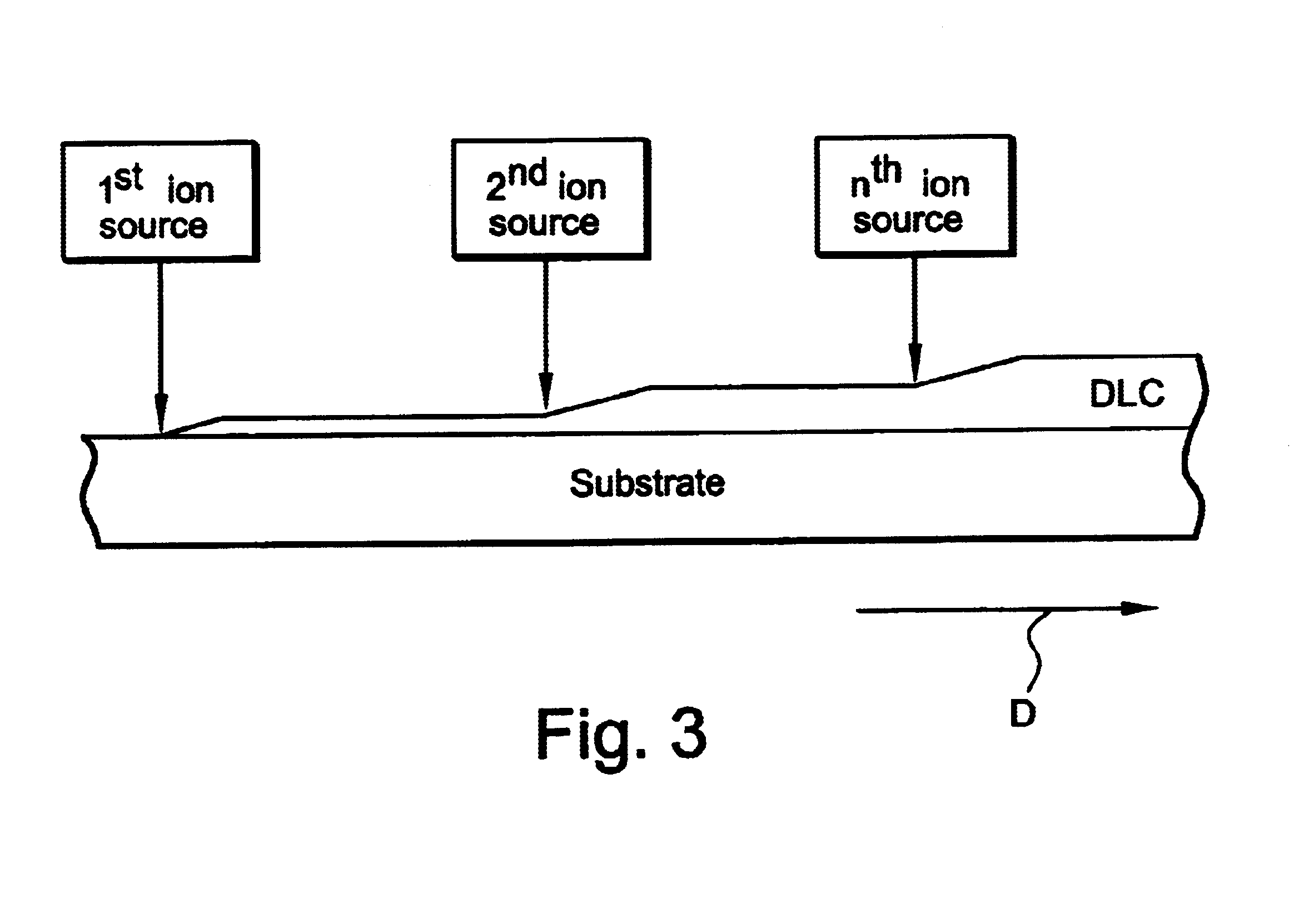
Surprisingly, it has been found that durability and / or longevity of a diamond-like carbon (DLC) layer can be improved by varying the voltage (and / or ion energy) used to ion beam deposit the DLC layer. In particular, a low voltage (voltage between the anode and cathode of the ion source) is used to ion beam deposit a first portion of the DLC layer on the substrate, and thereafter the voltage is increased to a second higher voltage(s) which is used to ion beam deposit a second portion of the DLC layer over the first portion of the DLC layer. In such a manner, ion mixing at the bottom of the DLC layer can be reduced, and the longevity and / or durability of the DLC improved. Moreover, the use of the higher voltage(s) for the second portion of the DLC layer enables that portion of the layer to have a high density and thus better hardness / scratch resistance than the first portion of the DLC layer.

Problems solved by technology

Unfortunately, such Si-C bonds in the DLC layer are believed to be more susceptible to breaking down upon exposure to ultraviolet (UV) radiation and water (i.e., QUV) than are C—C and C—H bonds.
Thus, the presence of many Si-C bonds in a layer of DLC, especially a very thin layer of DLC such as from 20-100 Åthick, can lead to premature breakdown of the layer upon environmental exposure (i.e., reduced longevity).
Thus, it can be seen that DLC layers that are deposited using a constant voltage (especially a high voltage used to deposit a thin DLC layer) are problematic in that their lifetime is rather short due to the high amount of ion mixing at the glass / DLC interface.
This high amount of ion mixing, and the large number of resulting Si-C bonds, renders the DLC layer more susceptible to breaking down upon environmental exposure.

Method used


Image

  • Method of depositing DLC on substrate
  • Method of depositing DLC on substrate
  • Method of depositing DLC on substrate

Examples


Embodiment Construction

According to certain example embodiments of this invention, it has been found that durability and / or longevity of a diamond-like carbon (DLC) layer can be improved by varying the voltage and / or ion energy used to ion beam deposit the DLC layer. A low voltage (and / or low ion energy) is used to ion beam deposit a first portion of the DLC layer on the substrate, and thereafter a second higher voltage(s) (and / or second ion energy(ies)) is used to ion beam deposit a second portion of the DLC layer over the first portion of the DLC layer. In such a manner, ion mixing at the bottom of the DLC layer can be reduced, and the longevity and / or durability of the DLC improved. Moreover, the use of the higher voltage(s) for the second portion of the DLC layer enables that portion of the layer to have a high density and thus better hardness / scratch resistance than the first portion of the DLC layer.

This allows a thicker coating with an overall lower k value to be deposited. In particular, since the...


PUM

PropertyMeasurementUnit
Fractionaaaaaaaaaa
Fractionaaaaaaaaaa
Fractionaaaaaaaaaa

Abstract

Durability and / or longevity of a diamond-like carbon (DLC) layer can be improved by varying the voltage and / or ion energy used to ion beam deposit the DLC layer. For example, a relatively low voltage may be used to ion beam deposit a first portion of the DLC layer on the substrate, and thereafter a second higher voltage(s) used to ion beam deposit a second higher density portion of the DLC layer over the first portion of the DLC layer. In such a manner, ion mixing at the bottom of the DLC layer can be reached, and the longevity and / or durability of the DLC improved.

Description

This invention relates to a method of depositing diamond-like carbon (DLC) on a substrate (e.g., glass substrate), and / or to the resulting product. In particular, this invention relates to a method of depositing DLC on a substrate in a manner such that a first portion of the DLC is ion beam deposited using a first voltage(s) and a second subsequent portion of the DLC is ion beam deposited using a second higher voltage(s) so that the second portion of the DLC has a higher density than the first portion of the DLC.BACKGROUND OF THE INVENTIONTechniques for ion beam depositing DLC are known in the art. Typically, a layer of DLC which is ion beam deposited on a glass substrate is deposited using a constant voltage (or ion energy, which is related to but different than the anode-cathode voltage per se as will be explained below) thereby resulting in a layer of DLC having a constant density.For example, consider a situation where a layer of DLC is ion beam deposited directly on a glass sub...

Claims


Application Information

Patent Timeline
IPC IPC(8): C23C14/22C23C14/06
CPCC23C14/0605C23C14/221Y10T428/30
Inventor VEERASAMY, VIJAYEN S.THOMSEN, SCOTT V.
Owner GUARDIAN GLASS LLC
Learn More