
Lighting arrangement for the ignition lock of a motor vehicle

a technology for ignition locks and lighting arrangements, which is applied in the direction of lighting and heating apparatus, instruments, machines/engines, etc., can solve the problems of not having enough space for lighting arrangements of this kind, and a considerable amount of space in the ignition lock region

Inactive Publication Date: 2005-04-05
VISTEON GLOBAL TECH INC
View PDF8 Cites 26 Cited by
  • Summary
  • Abstract
  • Description
  • Claims
  • Application Information

AI Technical Summary

Benefits of technology

Another object of the invention is to provide an ignition lock lighting arrangement which is easy to fit and permits fitting thereof jointly with an immobilizer on the ignition lock.
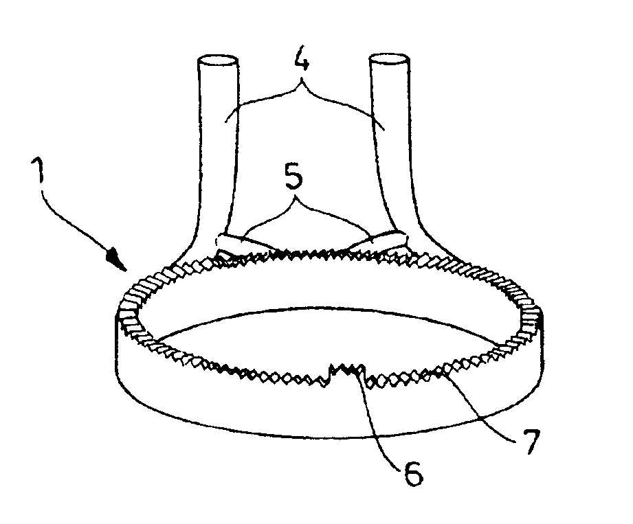
The lighting arrangement according to the invention can thus provide for dovetailing of the lighting effect and the immobilizer, which in the constricted space around the ignition lock makes it possible to achieve a considerable saving in space. By virtue of the light source being disposed in the housing of the immobilizer, not only is a saving made in respect of a separate lamp housing, but also the electrical feed lines which are provided in any case for the immobilizer are advantageously used for supplying power to the light source. There is therefore no longer any need for specific electrical supply lines to the light source.
In a preferred feature the light source can be formed by at least one surface-mounted light emitting diode (SMD-LED) on the circuit board of the immobilizer. A circuit board is generally already provided in electronic immobilizers for carrying the electronic control system. Therefore, at minimum cost and manufacturing expenditure, it is possible for one or more light emitting diodes to be additionally arranged on the circuit board and supplied with power. It is also advantageous in that respect that light emitting diodes are distinguished by a low level of current consumption with a high light yield.
Preferably the ring extension on the housing cover, which extends around the light ring, is of a reflecting configuration at the side which is towards the light ring. For example, the side towards the light ring may have a white coating or color. That maximizes the light yield from the light ring as light which issues in the direction of the cover member is reflected back into the light ring by the surface of the cover member and is thus available again for emission to the ignition lock.
The light-guide extension or extensions connecting the light ring and the light source preferably communicate substantially tangentially with the light ring. That provides that the light which is directly substantially in the direction of the light-guide extensions also passes virtually tangentially into the light ring and therefore can cover therein a maximum possible distance. That can also provide that an adequate amount of light for emission on to the ignition lock can still be provided even at a relatively great distance from the point of entry of the light into the light ring.
The depth and / or position of the notches is preferably not identical at every location on the light ring but may vary in accordance with the distribution of light which is to be afforded when light is shone therein. Without notches that distribution of light will not be uniform around the light ring, but will involve a maximum in the proximity of the light-guide extensions and a minimum at the greatest distance therefrom. By means of a suitable choice in respect of the depth and position of the notches however it is possible to correct that irregular light distribution to the effect that substantially uniform emission of light is achieved around the entire light ring.

Problems solved by technology

A disadvantage with the above-discussed arrangements is that they require a considerable amount of space in the region of the ignition lock, by virtue of the presence of the lamp which is to be disposed in the proximity of the light ring.
Frequently therefore there is no longer sufficient space for arrangements of that kind in modern motor vehicles with an immobilizer fitted to the ignition lock.

Method used


Image

  • Lighting arrangement for the ignition lock of a motor vehicle
  • Lighting arrangement for the ignition lock of a motor vehicle

Examples


Embodiment Construction

Referring firstly to FIG. 1 the assembly shown therein for an ignition lock (not shown) of a motor vehicle represents a combination of an ignition lock lighting arrangement with an immobilizer. The immobilizer has a housing 2, a coil (not shown) and a circuit board indicated at 8 in FIG. 3 for receiving an electronic control system. Such a module of an electronic mobilize is pushed in known manner in latching engagement on to the housing of an ignition lock (not shown).

As can be seen in particular from FIG. 3, in accordance with the invention a light ring 1 of light-guiding material is mounted releasably to the housing 2 of the immobilizer. The immobilizer and the light ring 1 are jointly covered by a housing cover shown at 3 in FIG. 1 which can be fitted by latching engagement into the housing 2 of the immobilizer. An annular extension of the housing cover 3 in that case extends around the light ring in positively locking relationship therewith in order to fix it and to prevent lig...


PUM


Abstract

A lighting arrangement for the ignition lock of a motor vehicle has a light ring comprising a translucent material and fitted on to the housing of an engine immobilizer of the vehicle. Light-guide extensions in leg form lead to the light ring from light emitting diodes on the circuit board of the immobilizer. Preferably arranged at the side of the light ring which is towards the ignition lock are notches for producing a light-dark pattern, wherein the notch depth and position can vary for the purposes of producing a uniform emission of light.

Description

FIELD OF THE INVENTIONThe invention generally concerns a lighting arrangement for an ignition lock of a motor vehicle.BACKGROUND OF THE INVENTIONA typical lighting arrangement for a motor vehicle ignition lock includes a light ring which comprises a light-guiding material. The light ring surrounds the ignition lock and has light-guide extensions leading to a light source to feed light to the light ring.A lighting arrangement of that kind can be found in EP 0 475 146 A1. It comprises a sleeve-shaped light ring which extends around the ignition lock of a motor vehicle to produce a homogeneous lighting effect, and a cover which is releasably secured to the light ring and which extends around it in positively locking relationship. Integrated into the cover is a lamp housing for accommodating a lamp serving as the light source. The light of the lamp is deflected through 90° by way of light-deflecting prisms and introduced into the light ring by way of light-introducing limbs.A similar li...

Claims


Application Information

Patent Timeline
IPC IPC(8): B60Q3/02B60Q3/00E05B17/00E05B17/10
CPCB60Q3/004E05B17/10B60Q3/02B60Q3/292B60Q3/64
Inventor VERLAGE, ALWINBAUMGARTEN, LARS
Owner VISTEON GLOBAL TECH INC
Learn More