
Measurement head for atomic force microscopy and other applications

Inactive Publication Date: 2005-03-29
RGT UNIV OF CALIFORNIA
View PDF7 Cites 29 Cited by
  • Summary
  • Abstract
  • Description
  • Claims
  • Application Information

AI Technical Summary

Benefits of technology

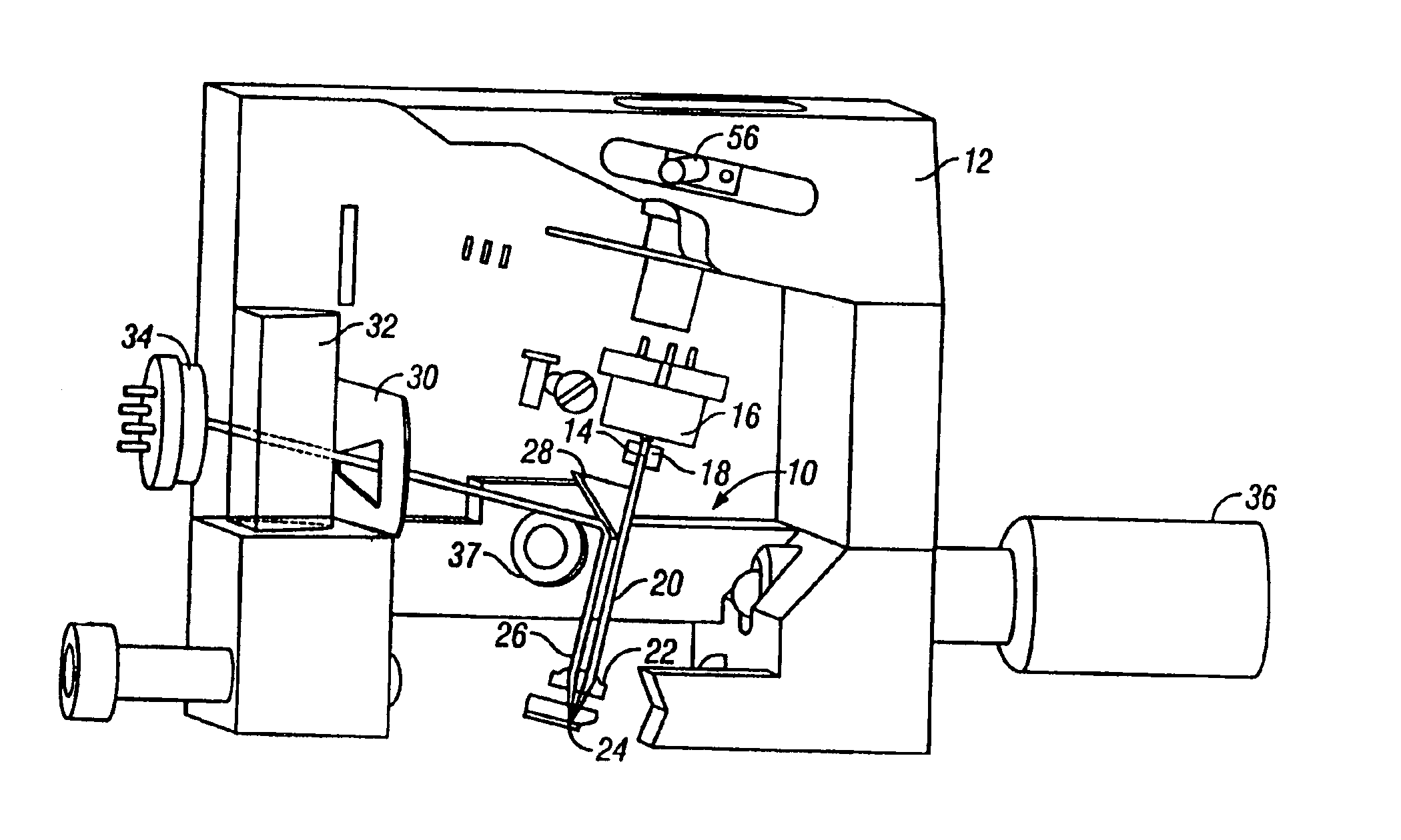
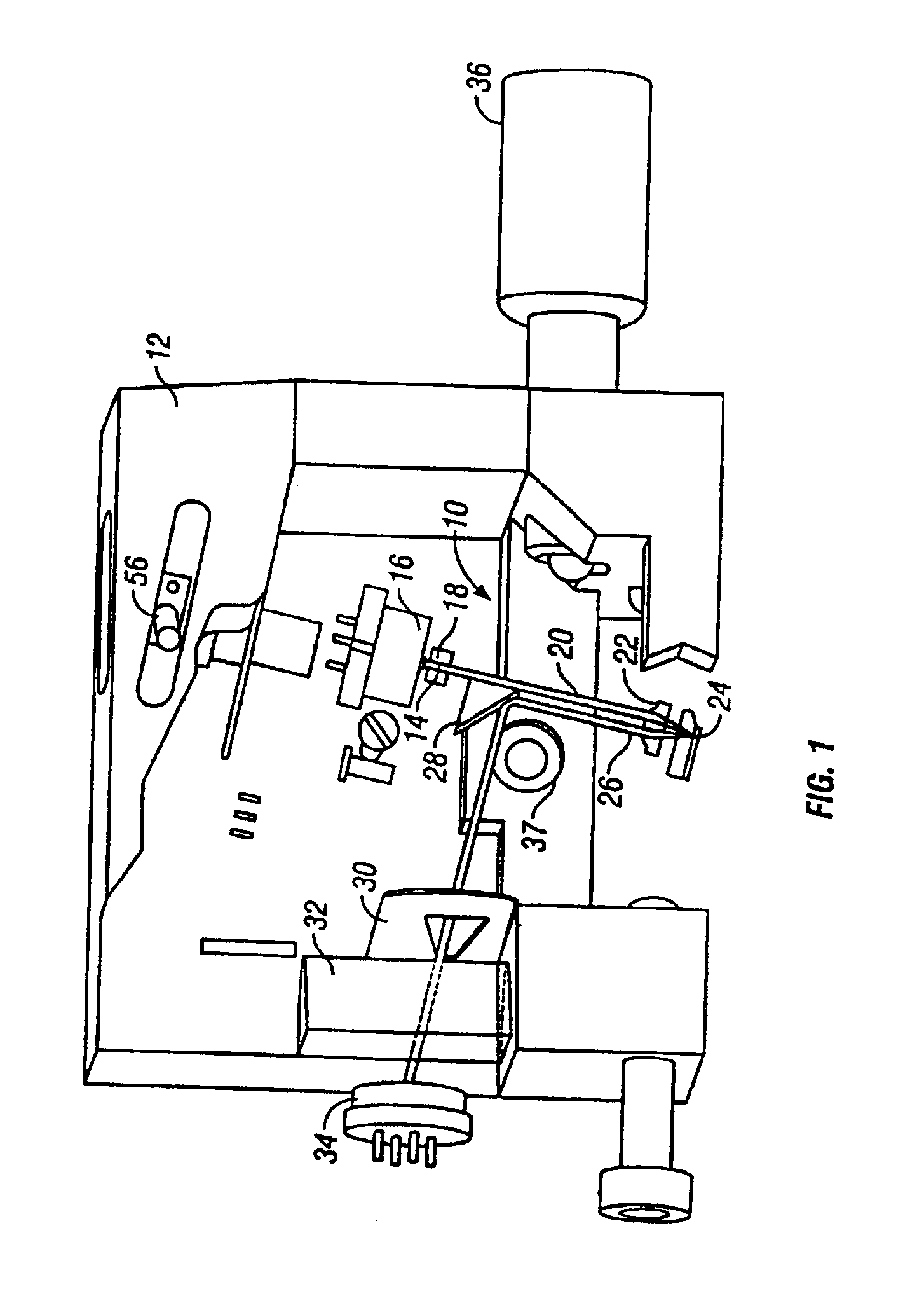
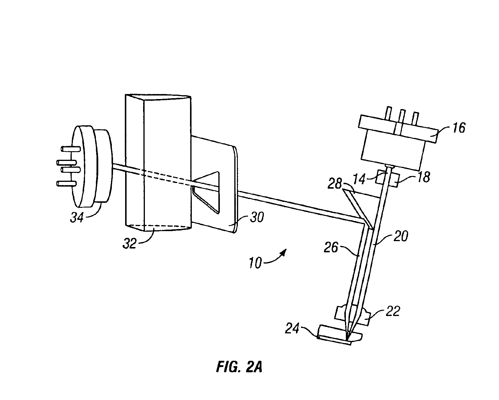
The present invention provides improvements for the optical tracking and detection of reflected light beams that has general application to any optical system for measuring the motion of a cantilever, and specific application to AFMs. In particular, the present invention provides an improved AFM head that has significant novel features and advantages over existing AFM heads. A particular novel feature is the use of a novel optical path wherein different regions of an objective lens are used for incident and reflected light. A second novel feature of this AFM is the unified optics block that contains all the optical elements of the optical lever detection system between and encompassing the light source and the final focusing lens in an extremely small and rigid package. Another novel feature is that the beam from the AFM light source never hits a flat surface at normal incidence except when it is strongly diverging or converging. A further novel feature is a three dimensional flexure to allow three dimensional motion of the optics block. Another novel feature is enabling resonant frequencies of greater than 850 Hz for two mechanical paths that most affect the performance of the AFM: the mechanical paths from the cantilever to the sample, and between the cantilever and the focusing lens. This is aided by kinematically indexing the cantilever holder directly to the top of the piezoelectric scanner to provide a direct mechanical path between the sample on top of the scanner and the cantilever. Still another novel feature, which improves both AFMs and STMs and other scanning probe microscopes, is the use of composite materials or ceramics for making housings, optics blocks, and other components of scanning probe microscopes, providing desired high stiffness and a low thermal expansion coefficient.

Problems solved by technology

This has introduced problems relating to the sensitivity of the instrument.

Method used


Image

  • Measurement head for atomic force microscopy and other applications
  • Measurement head for atomic force microscopy and other applications
  • Measurement head for atomic force microscopy and other applications

Examples


Embodiment Construction

In accordance with an embodiment of this invention, a measurement head is provided that can be used to measure the deflections of a cantilever and other nanomechanical devices and features. The most common application of this measurement head is as the detection head of an atomic force microscope, but this measurement head can also be used to make precise measurements of the motion of any nano size feature or structure or nanomechanical object, that is a feature or object where the motions on the nanometer scale are important for the operation of the device. Further, many of the principals of this measurement head can be used to provide an improved capability to measure the vertical and / or lateral motion of arbitrary objects at the nanometer scale.

These deflections are related to the force on the cantilever and can be used for measuring forces vs. distance curves, for measuring a force to be controlled by a feedback network during imaging and for the many uses that have been already...


PUM


Abstract

An improvement for atomic force microscopes, more generally for light beam detecting systems, but also in part applicable to scanning probe microscopes, providing significant novel features and advantages. Particular features include using different objective lens regions for incident and reflected light, a flexure that allows three dimensional motion of the optics block, forming the housing and optics block of a composite material or ceramic, arranging the components so that the beam never hits a flat surface at normal incidence, and providing a resonant frequency of cantilever vibration greater than 850 HZ between the cantilever and sample and the cantilever and focusing lens.

Description

FIELD OF THE INVENTIONThis invention relates to the field of scanning probe devices. More particularly, the invention relates to improvements in an atomic force microscope used to measure the deflections of a cantilever.BACKGROUND OF THE INVENTIONScanning probe devices, such as the atomic force microscope (AFM) have proven to be excellent tools for imaging a wide range of materials, such as metals, semiconductors, minerals, polymers, and biomaterials. In an AFM, forces are measured by means of a cantilever that deflects when forces act on it. The deflection of the cantilever is sensed by a detection system, commonly by focusing an incident beam as a spot onto the cantilever and directing the reflected beam onto a segmented detector. Specialized AFMs called “force pullers” have been built for the purpose of pulling on molecules to determine the structure and dynamics of those molecules. AFM-like cantilevers and cantilever arrays have also been used recently as chemical sensing device...

Claims


Application Information

Patent Timeline
IPC IPC(8): G12B21/22G12B21/00G12B21/08G01Q20/02G01Q30/02G01Q60/24G01Q60/38G01Q60/58
CPCB82Y35/00G01Q60/38G01Q20/02
Inventor HANSMA, PAUL K.DRAKE, BARNEYTHOMPSON, JAMESKINDT, JOHANNES H.HALE, DAVID
Owner RGT UNIV OF CALIFORNIA
Learn More