
Branching RF antennas and plasma processing apparatus

a plasma processing apparatus and rf antenna technology, applied in the direction of coatings, electric discharge lamps, electric lighting sources, etc., can solve the problems of inability to generate uniform plasma, rf antennas are not able to provide the required plasma homogeneity, and traditional spiral rf antennas are becoming too long for larger wafers or lcd substrates, etc., to achieve improved plasma material processing, reduce standing wave effects, and improve plasma generation uniform

Inactive Publication Date: 2005-03-22
TOKYO ELECTRON LTD
View PDF3 Cites 33 Cited by
  • Summary
  • Abstract
  • Description
  • Claims
  • Application Information

AI Technical Summary

Benefits of technology

It is another object of the present invention to improve the uniformity of plasma generation.
It is still another object of the present invention to reduce standing wave effects for improved plasma material processing.
In a first aspect of the present invention, the branching RF antenna comprises a plurality of major and minor branches with embedded cooling channels extending from a central feed element. This preferred embodiment provides more homogenous plasma generation and thus more uniform coverage of the plasma area.

Problems solved by technology

The growing demands for processing larger and larger wafers or LCD (liquid crystal display) substrates and providing higher and higher degrees of plasma uniformity challenge the current ICP type antenna designs and push development of sources.
Traditional spiral RF antennas are becoming too long for larger wafers or LCD substrates and cannot generate uniform plasmas.
Furthermore, such RF antennas are unable to provide the required plasma homogeneity in both, flat and dome-shaped, geometries.
Problems with RF antennas occur due to the lengthening of antenna elements relative to the electromagnetic wave and because of the standing wave effects.
The standing wave effects become stronger during increased frequency operation of increased wafer or substrate size, limiting the RF antenna's area of application and reducing uniformity.
In addition, radially extended RF antennas are becoming non-efficient because they are not able to uniformly cover the entire plasma processing area over the substrate.
Area coverage reduces outwardly from the endpoint such that there is satisfactory coverage closer to the center of the antenna, but unsatisfactory coverage between any two radially extending “arms” of the antenna.
The dome-type antennas are similarly unable to perform adequately given the increasing size of the plasma area and substrates.
Finally, the antennas wired around the sides of the vacuum chamber are becoming inefficient because they cannot provide adequate RF fields in the inner half of the plasma volume.

Method used


Image

  • Branching RF antennas and plasma processing apparatus
  • Branching RF antennas and plasma processing apparatus
  • Branching RF antennas and plasma processing apparatus

Examples


Embodiment Construction

Embodiments of the present invention will be described hereinafter with reference to the accompanying drawings. In the following description, the constituent elements having substantially the same function and arrangement are denoted by the same reference numerals, and repetitive descriptions will be made only when necessary.

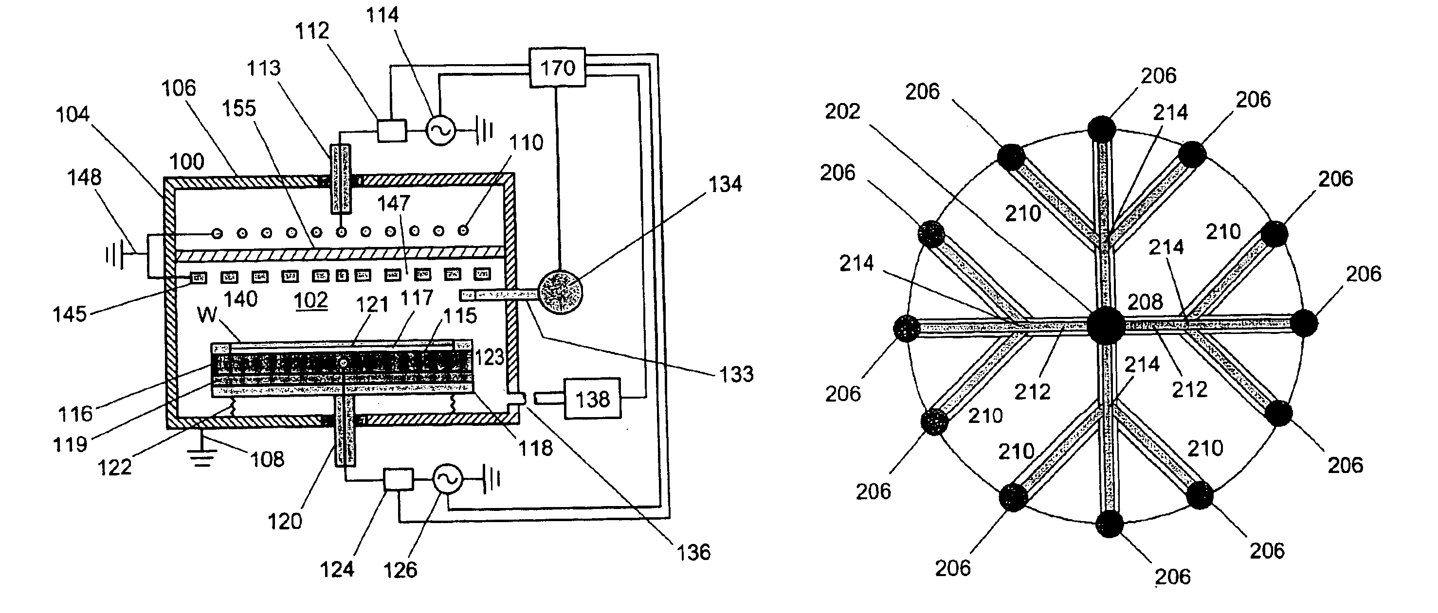
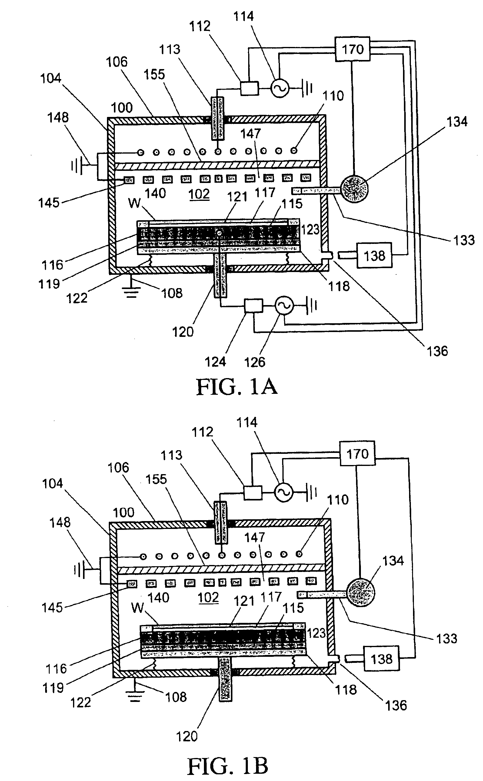
FIG. 1a is a schematic diagram showing a plasma etching system 100 according to a preferred embodiment of the present invention. Plasma etching system 100 comprises an ICP source having a branching antenna.

An airtight process chamber 102 of plasma etching system 100 is constituted by a substantially cylindrical process vessel 104 and top plate 106. Process vessel 104 and top plate 106 are made of a conductive material, such as stainless steel and are grounded through ground line 108.

Faraday shield 140 is electrically coupled to the sidewalls of process vessel 104.

In the illustrated embodiment, Faraday shield 140 comprises a number of conductive elements 145 and ...


PUM

PropertyMeasurementUnit
Angleaaaaaaaaaa
Dielectric polarization enthalpyaaaaaaaaaa
Poweraaaaaaaaaa

Abstract

The inductively coupled plasma source and antenna geometry are significant factors in determining plasma and process uniformity inside the chamber. Growing demands for processing larger and larger wafers or LCD substrates and providing higher and higher degrees of plasma uniformity challenge the current ICP type antenna designs and push development of sources. Branching RF antenna, featuring a plurality of major and minor branches, provides improved coverage of processing area, reduced standing wave effect, improved uniformity of inductively coupled electromagnetic field, more uniform plasma production, and more homogeneous processing conditions throughout the whole processing area.

Description

FIELD OF THE INVENTIONThe present invention relates generally to a plasma material processing apparatus and more particularly to apparatus for and method of plasma generation of the induction coupling type in which induction plasma is excited by applying electromagnetic energy to a branching RF antenna.BACKGROUND OF THE INVENTIONMany types of plasma material processing methods are widely accepted for semiconductor fabrication and plasma generation including: sputter etching, plasma-enhanced chemical etching, reactive ion etching, plasma-enhanced vapor deposition, ionized sputter deposition and magnetically enhanced plasma etching. Different types of well-known plasma sources are used in these processes such as the popular inductively coupled plasma (ICP) sources as well as others including: capacitively coupled plasma (CCP) sources, microwave plasma sources (including those that utilize the electron-cyclotron resonance for improved efficiency of power deposition into the plasma), su...

Claims


Application Information

Patent Timeline
IPC IPC(8): H01J37/32
CPCH01J37/321H01J37/32091
Inventor MOROZ, PAUL
Owner TOKYO ELECTRON LTD
Learn More