
Method of manufacturing a structural frame

a manufacturing method and technology for structural frames, applied in the direction of electrical apparatus construction details, conductive pattern formation, modification by conduction heat transfer, etc., can solve the problems of destroying the microprocessor device itself or other components proximal to the microprocessor, and increasing the size of the device. , to achieve the effect of enhancing thermal dissipation

Inactive Publication Date: 2005-03-22
TICONA POLYMERS INC
View PDF28 Cites 24 Cited by
  • Summary
  • Abstract
  • Description
  • Claims
  • Application Information

AI Technical Summary

Benefits of technology

The invention is generally directed to a novel and unique electronic device construction, employing a structural frame that includes an improved heat dissipating system for cooling heat generating devices and circuit boards attached thereto. The structural frame of the present invention enables the cost-effective cooling of electronic devices while realizing superior thermal conductivity and providing improved electromagnetic shielding.
In accordance with the present invention, a structural frame for dissipating heat from an electronic device is provided. The electronic device includes an electronic circuit board with a heat generating electronic component installed thereon, mounted to the frame of the present invention. The heat generating components on the circuit board are installed in such a manner as to be in thermal communication with the frame so that the heat generated can be dissipated through the frame and away from the electronic device. In addition, outer covers or case components are mounted to the structural frame to protect the internal components and provide the finished shape of the device.
The structural frame is be injected molded from a net shape moldable thermally conductive polymer composition. Some of the surfaces of the frame are located along the external surfaces of the device so as to provide a point at which heat can be effectively dissipated as it is conducted from the interior of the device through the thermally conductive frame. As the structural frame of the present invention is fabricated from plastic materials it is lighter than the structural materials previously employed. In addition, the present invention also has the advantage of being net shape moldable, meaning, the part that is created in the injection molding process does not require any further processing steps after it is removed from the mold and before it is incorporated into the finished device. Both the lighter weight and the net-shape moldability are distinct advantages over the prior art where metallic parts had to be machined in several steps to achieve the desired part geometry.
Another feature of the present invention is the electromagnetic interference (EMI) shielding provided. Normally a separate EMI shield is installed in an electronic device. The shield acts as a shroud around the electronic component to shield it from electromagnetic interference. However, such a shield effectively encases the electronic component making access thereto for dissipating heat very difficult, if not impossible. Further, the EMI shield encasement prevents airflow to the electronic component for cooling. Since the structural frame is constructed from thermally conductive polymers it inherently absorbs EMI waves and prevents their transmission to the electronic circuitry inside the device without the installation of an additional component. This feature is particularly important in applications such as cellular telephones where EMI waves can prevent the device from functioning properly. Thus a thermally conductive polymer frame can effectively dissipate the heat generated within the device while shielding the electronic components from EMI waves without the addition of a separate EMI shield part that could potentially interfere with the heat transfer from the device.
It is therefore an object of the present invention to provide a structural frame for an electronic device that enhances the dissipation of heat from a heat generating electronic component mounted thereto.
It is a further object of the present invention to provide a structural frame for an electronic device that is injection moldable from a thermal composite material into complex geometries to enhance thermal dissipation.

Problems solved by technology

For example, the CPU within the Cassiopeia, a microprocessor containing millions of transistors, is highly susceptible to overheating which could destroy the microprocessor device itself or other components proximal to the microprocessor.
As a result, heat generation and overheating continues to be a serious concern while the sizes of the devices get smaller.
Therefore, problems arise as to how to effectively cool the small electronic components within the small and cramped environments within the device.
Typical cooling solutions such as heat sinks and fans are not preferred because they are large and, as a result, consume large spaces within an already cramped electronic device case.
In addition, since these small devices, such as cellular phones or laptop computers, must balance competing demands for higher power requirements, smaller battery sizes with the associated power limitations and overall device case size, active cooling solutions, such as powered fans and the like, are not desirable.
Although these materials allowed for heat transfer, they are not as lightweight as plastics and are difficult to fabricate into the compact and complex shapes required for the small electronics devices.
In addition, electromagnetic interference shielding is often required to ensure proper operation of the electronic device.
However, the metallic structural frames provide no shielding and the use of traditional EMI shielding, which typically encase the electronic component within the device to be protected, obstructs proper installation and use of effective solutions for cooling the same electronic component.

Method used


Image

  • Method of manufacturing a structural frame
  • Method of manufacturing a structural frame
  • Method of manufacturing a structural frame

Examples


Embodiment Construction

For illustration purposes only, and by way of example, the present invention is shown to be employed for a cellular telephone. As will be seen below, the structural frame for the electronic device of the present invention can be easily employed in the fabrication of other electronic devices, such as laptop computers and personal digital assistants, for example. The invention will be described in detail below in the context of an application for a cellular telephone; however, such disclosure is not intended to limit the scope of the present invention to such an application of the present invention.

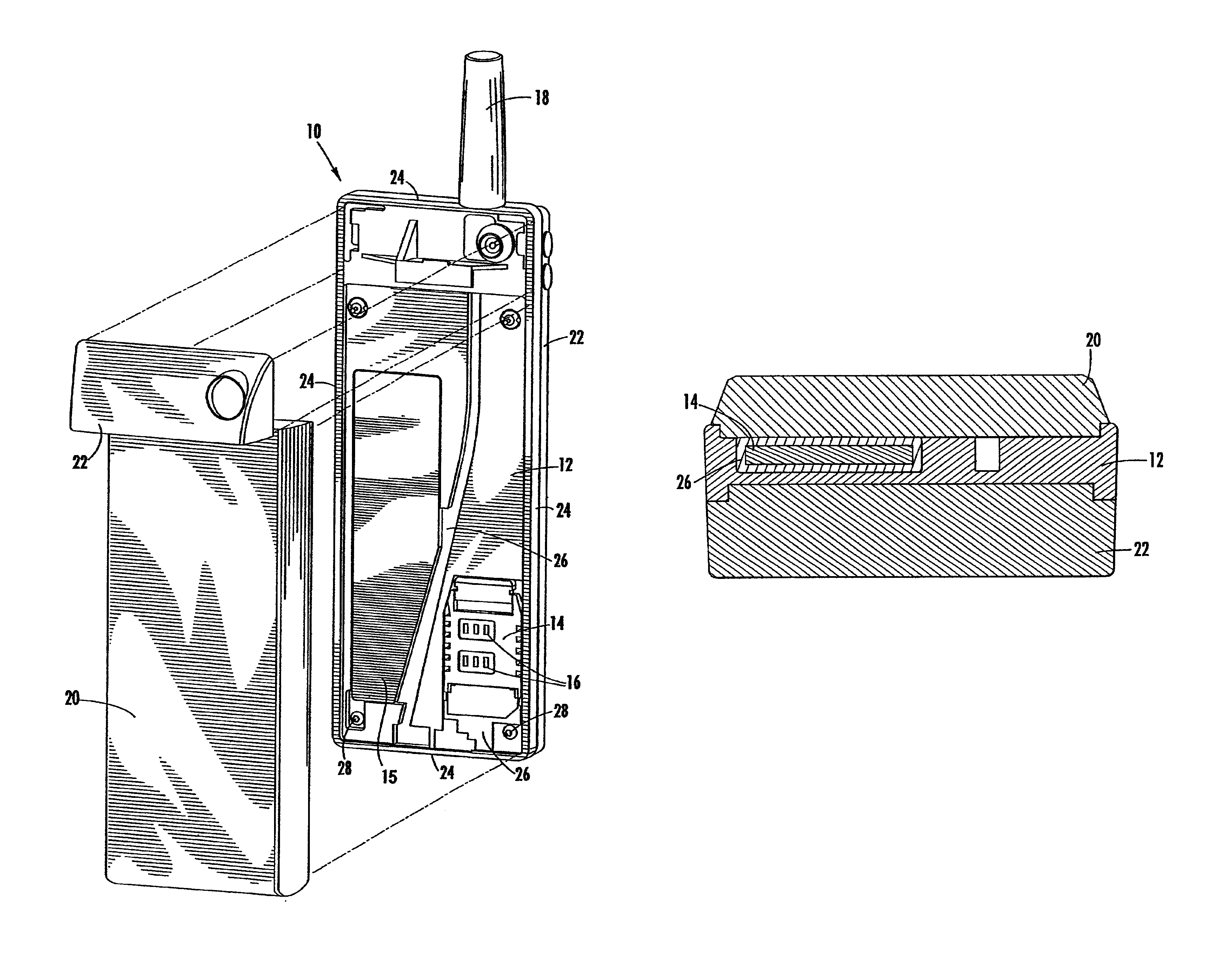
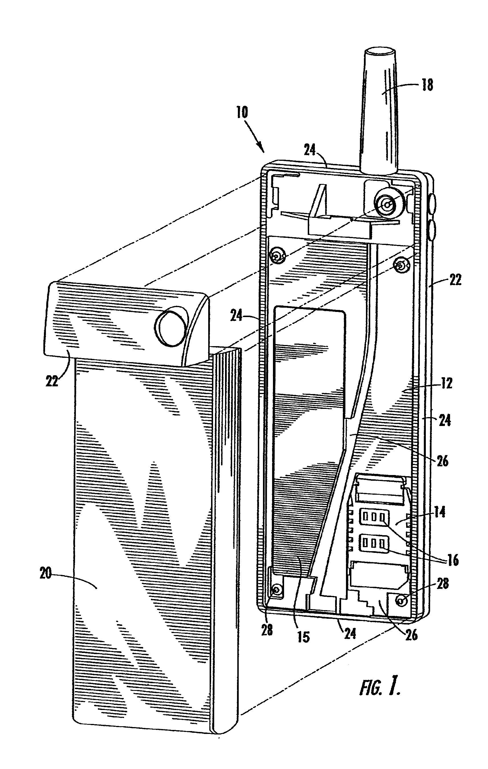
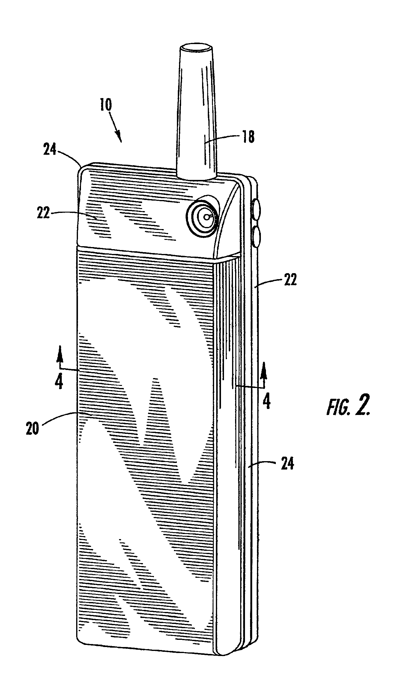
The preferred embodiment of the present invention is shown in FIGS. 1-4. In FIG. 1, an exploded perspective view of the preferred embodiment is shown to include an electronic device that has a snap together modular construction in the form of a cellular telephone 10. The cellular telephone 10 includes a structural frame 12 with a circuit board 14 mounted thereupon. A number of heat generati...


PUM

PropertyMeasurementUnit
thermally conductiveaaaaaaaaaa
thermal conductivityaaaaaaaaaa
heataaaaaaaaaa

Abstract

A structural frame (12) for dissipating heat from an electronic device (10) is provided. The structural frame (12), to which an electronic circuit board (14) containing a heat generating electronic component (16) is mounted, is injection molded from a thermally conductive, net-shape moldable polymer composition. The electronic component (16) that is within the device (10) is in thermal communication with the structural frame (12), so that the heat generated within the device (10) is transferred to the frame (14) and dissipated from the heat-generating device (10). An outer case (22) may be mounted to the frame (12) to finish the device (10) or the frame (12) may serve as all or a part of the outer device case (22) as well. In addition, the structural frame (12) has characteristics that may be engineered and used to shield the device (10) from electromagnetic interference.

Description

BACKGROUND OF THE INVENTIONThe present invention relates generally to electronic devices, integrated circuit components and structural mounting frames for assembling such components. More specifically, the present invention relates to creating structural components for these devices that also function for dissipating the heat generated within such devices.In the small electronics and computer industries, it has been well known to employ various types of electronic component packages and integrated circuit chips, such as the central processing chips employed within cellular telephones and the central processing units (CPU's) used within palmtop computers like the Cassiopeia manufactured by Casio. These integrated circuit chips have a pin grid array (PGA) package and are typically installed into a socket, or are soldered directly onto a computer circuit board. These integrated circuit devices, particularly the CPU microprocessor chips, generate a great deal of heat during operation wh...

Claims


Application Information

Patent Timeline
Patent Type & Authority Patents(United States)
IPC IPC(8): H04B1/02H04B1/036H05K7/20
CPCH04B1/036H05K7/20509Y10T29/4913Y10T29/49172Y10T29/49158Y10T29/49146Y10T29/49126Y10T29/49155
Inventor MCCULLOUGH, KEVIN A.
Owner TICONA POLYMERS INC
Learn More