
Method of forming a flexible insulation blanket having a ceramic matrix composite outer layer

a technology of ceramic matrix and flexible insulation, which is applied in the direction of transportation and packaging, other domestic objects, mechanical equipment, etc., can solve the problems of unsuitable vehicles' windward surfaces or vehicles' surfaces, the outer layer of fabric does not provide a uniform substrate for forming a flat, smooth surface, and the use of traditional flexible blankets. achieve the effect of complete insulative efficiency of the batting, reduce the overall temperature to which the blanket is exposed, and reduce the interference of the boundary layer

Inactive Publication Date: 2005-03-15
THE BOEING CO
View PDF12 Cites 18 Cited by
  • Summary
  • Abstract
  • Description
  • Claims
  • Application Information

AI Technical Summary

Benefits of technology

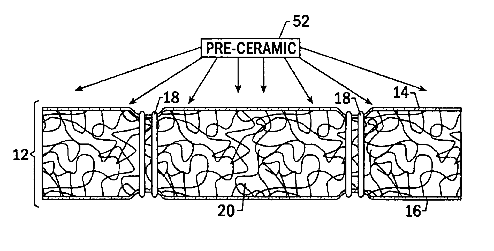
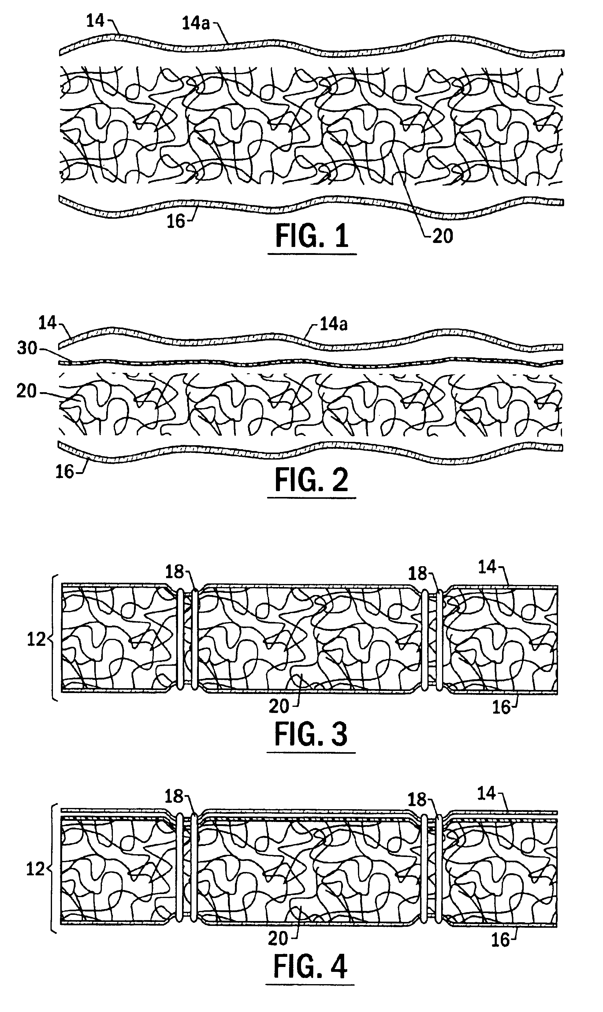
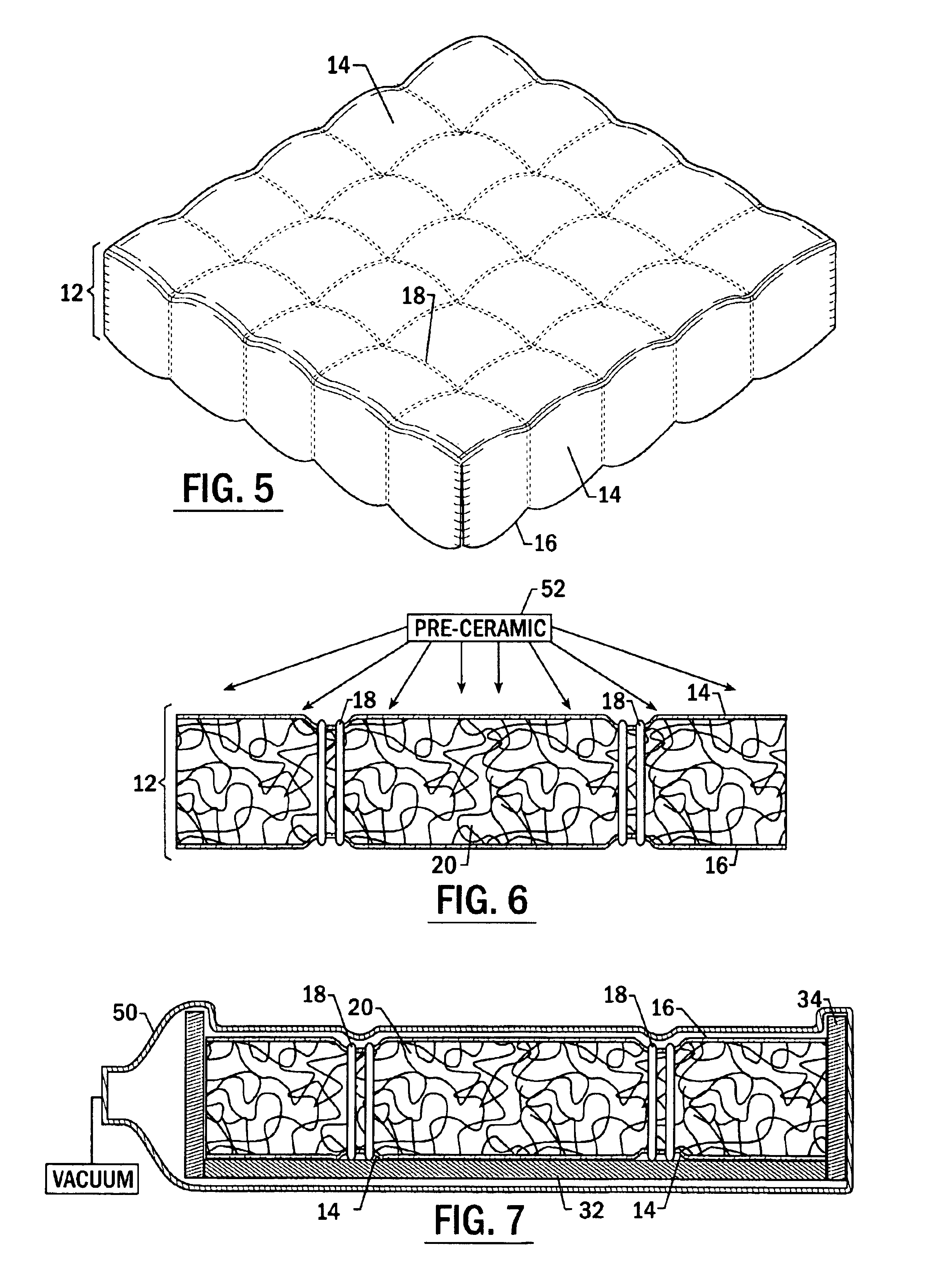
The invention is a flexible insulation blanket having a ceramic matrix composite (CMC) outer layer, and a method of producing a flexible insulation blanket having a smooth, aerodynamically suitable, outer surface by infiltrating ceramic material within the outer ceramic fabric layer of the flexible insulation blanket and curing the ceramic material to form a CMC layer. The CMC layer is cured while the blanket is under compression such that the resulting CMC layer has a smooth surface.
It is desirable to use the invented flexible blankets on windward surfaces of spacecraft rather than ceramic tiles because blankets can be put on in large sizes such as 36 inches by 36 inches, compared to 6 inches by 6 inches for tiles, due to their inherent flexibility and built in strain isolation. This reduces assembly, part count and operation maintenance. The large, smooth blankets also reduce the steps and gaps typically found between the 6 inch by 6 inch tiles.

Problems solved by technology

There are some drawbacks associated with the use of traditional flexible blankets.
Further, because the outer layer of fabric and the batting are loosely quilted together, the outer layer of fabric does not provide a uniform substrate for forming a flat, smooth surface.
The rough and irregular surfaces of flexible insulation blankets have heretofore made them unsuitable for use on windward surfaces of vehicles or surfaces of vehicles which experience relatively high temperatures, such as the nose section and leading edges of the vehicle.
When in use, the irregular surface of the blankets causes early tripping of the boundary layer as well as increased friction along the surface of the vehicle upon reentry, thereby generating large amounts of excessive heat.
Therefore, flexible insulation blankets have only been used upon leeward surfaces of the RLV's which do not experience aero turbulence or high temperatures during reentry.

Method used


Image

  • Method of forming a flexible insulation blanket having a ceramic matrix composite outer layer
  • Method of forming a flexible insulation blanket having a ceramic matrix composite outer layer
  • Method of forming a flexible insulation blanket having a ceramic matrix composite outer layer

Examples


Embodiment Construction

The present invention now will be described more fully hereinafter with reference to the accompanying drawings, in which preferred embodiments of the invention are shown. This invention may, however, be embodied in many different forms and should not be construed as limited to the embodiments set forth herein; rather, these embodiments are provided so that this disclosure will be thorough and complete, and will fully convey the scope of the invention to those skilled in the art. Like numbers refer to like elements throughout.

Referring to FIG. 1, the CMC coated flexible insulation blanket of the invention is constructed of various layers of material. It is anticipated that the invented insulation will be most often used to insulate the outer surface of a spacecraft such as the Space Shuttle though the insulation is not limited to such use. For purposes of this description, “outer” or “Outer Mold Line (OML)” components are those components, which are disposed at a greater distance fro...


PUM

PropertyMeasurementUnit
thicknessaaaaaaaaaa
temperatureaaaaaaaaaa
temperaturesaaaaaaaaaa

Abstract

A flexible insulation blanket having a ceramic matrix composite (CMC) outer layer, and a method of producing a flexible insulation blanket having a smooth, aerodynamically suitable, outer surface by infiltrating ceramic material within the outer ceramic fabric layer of the flexible insulation blanket and curing the ceramic material to form a CMC layer. The CMC layer is cured while the blanket is under compression such that the resulting CMC layer has a smooth surface.

Description

FIELD OF THE INVENTIONThe invention relates to flexible reusable surface insulation blankets for use on the outer surface of reusable launch vehicles. More particularly, the invention relates to ceramic coatings and methods of coating the outer mold line surface of insulation blankets.BACKGROUND OF THE INVENTIONReusable launch vehicles (RLV's) such as the Space Shuttle Orbiter utilize reusable thermal protection systems (TPS's) for thermal protection during launch, orbit, and reentry into the atmosphere. The TPS must simultaneously perform as a radiator, a reflector, and an insulator in order to, respectively, emit heat from the surface of the vehicle, prevent on-orbit heating, and protect the structure of the vehicle from residual heat flux.During a typical reentry, the outer surface of the Orbiter is subjected to heating in excess of 2300° F. The underlying structure of the Orbiter is primarily aluminum and graphite epoxy, and the TPS must protect the structure from any temperatur...

Claims


Application Information

Patent Timeline
Patent Type & Authority Patents(United States)
IPC IPC(8): B32B18/00B32B3/06B32B9/00B64C1/00C04B35/00B32B5/02B32B5/26B32B5/30B32B17/02C04B35/447C04B35/80F16L59/02
CPCB32B5/02B32B5/30B32B17/02B32B18/00C04B35/447C04B35/6263C04B35/803F16L59/026B32B5/26Y10T428/26C04B2235/3224C04B2235/5224C04B2235/5228C04B2235/5232C04B2235/5244C04B2235/5256Y10S428/92Y10T428/24033C04B35/80Y10T428/249928
Inventor DENHAM, JERRYDICHIARA, JR., ROBERT A.HENG, VANNLEHMAN, LEANNE L.ZORGER, DAVID
Owner THE BOEING CO
Learn More