
Prosthetic joints having reduced area bearing surfaces and application thereof to a range of sizes of prosthetic joints

a technology of prosthetic joints and bearing surfaces, applied in the field of prosthetic devices, can solve the problems of reducing wear, affecting the function of prosthetic joints, so as to reduce the potential for dislocation, reduce contact area, and increase the range of motion

Inactive Publication Date: 2005-03-15
DEPUY ORTHOPAEDICS INC
View PDF1 Cites 68 Cited by
  • Summary
  • Abstract
  • Description
  • Claims
  • Application Information

AI Technical Summary

Benefits of technology

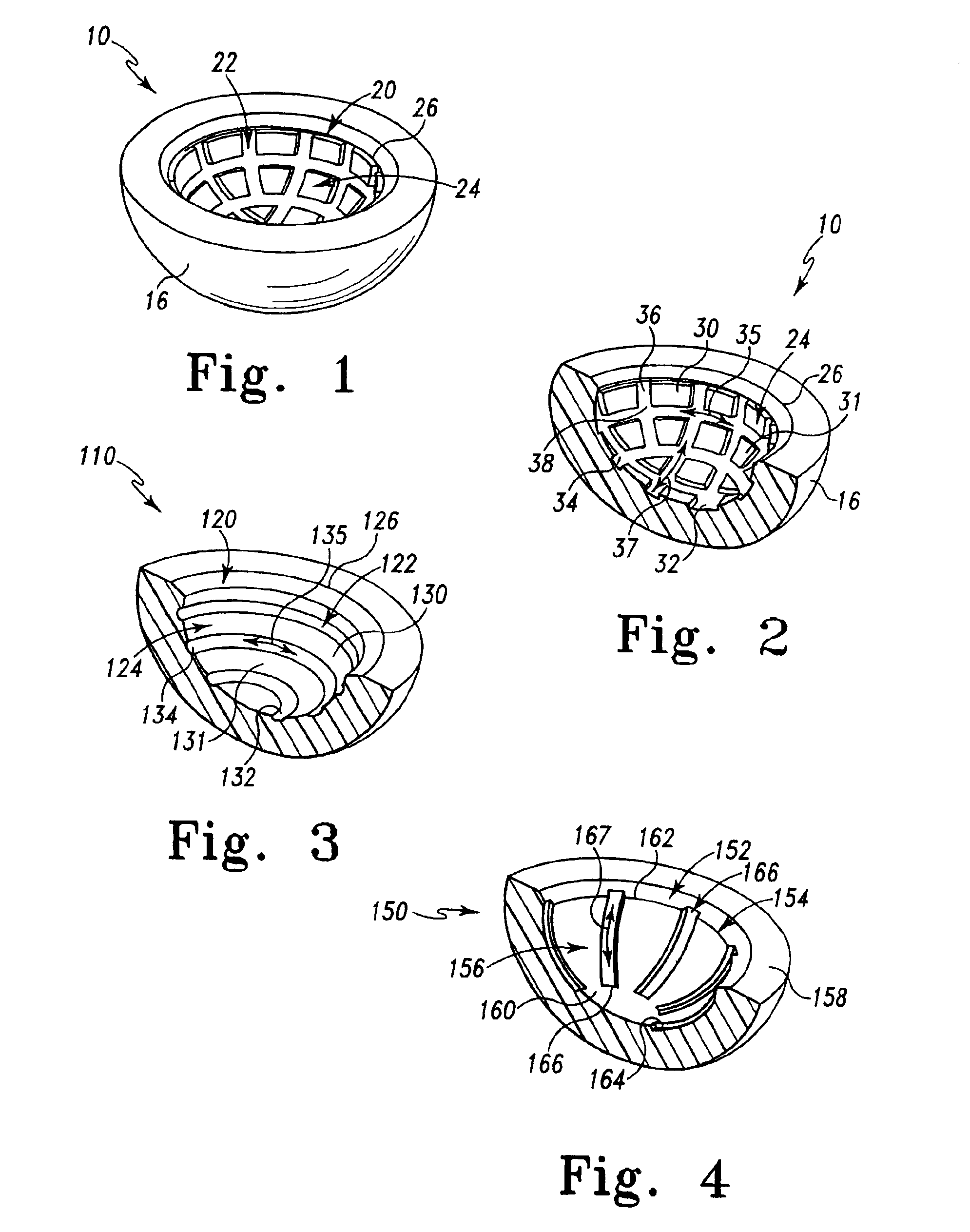
Optimally decreasing contact area in the articulating surface of one or both bearing components of the prosthetic assembly through interruptions in the surface thereof, provides benefits of larger diameter prosthetic components (with an associated increased range of motion, and decreased potential for dislocation), low frictional torques, and lower wear of smaller diameter prosthetic components.

Problems solved by technology

While conventional prosthetic components beneficially provide a low-friction articular face for the surface of accompanying member, interaction between the articulating component and the member can produce joint debris.
Such debris is expelled into the adjacent tissues and may cause adverse reactions in the surrounding bodily tissue.
For hard-on-hard bearing combinations of an acetabular cup assembly, for example, a lower head to cup clearance (gap) results in lower wear.
For polyethylene-on-hard bearing combinations, which have typically been smaller diameter implants, implant wear increases with implant diameter and decreasing clearance.

Method used


Image

  • Prosthetic joints having reduced area bearing surfaces and application thereof to a range of sizes of prosthetic joints
  • Prosthetic joints having reduced area bearing surfaces and application thereof to a range of sizes of prosthetic joints
  • Prosthetic joints having reduced area bearing surfaces and application thereof to a range of sizes of prosthetic joints

Examples


Embodiment Construction

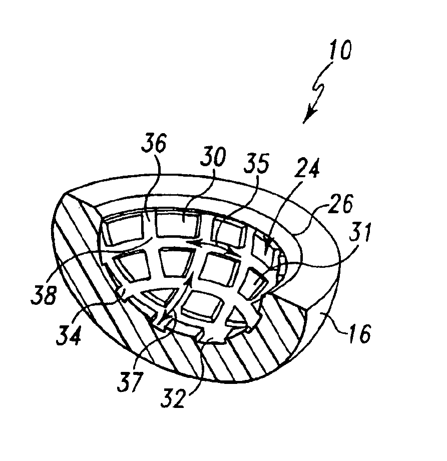
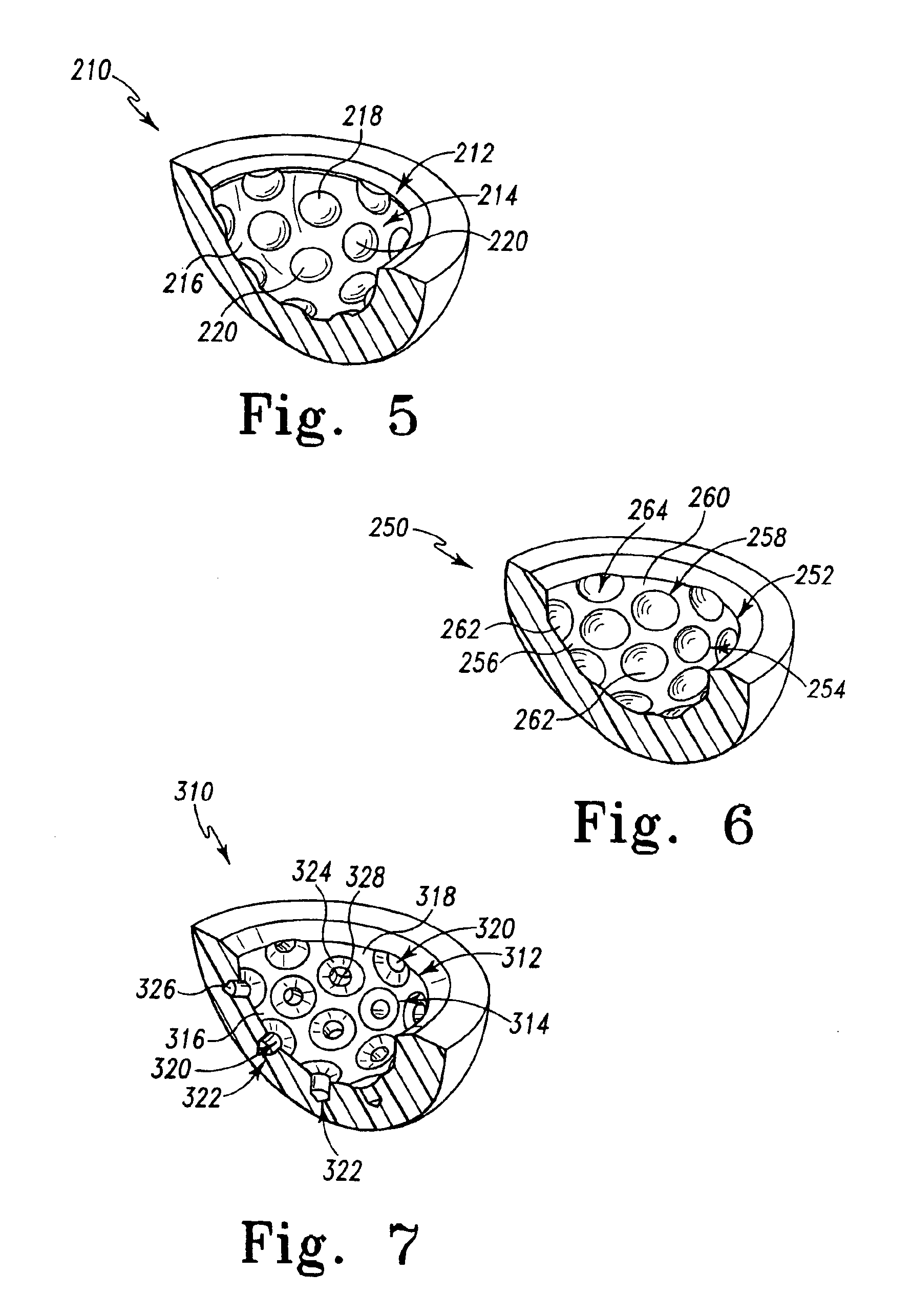
The subject invention is based upon a hypothesis and resulting principles that a prosthetic assembly having a bearing component with an articular face, interrupted by either recesses or protrusions, minimizes production of joint debris created by the interaction between the articular face and an accompanying joint face articulation component. This decrease is believed to be the result of the reduction in available surface area of articulation between the components, in comparison with traditional bearing components having smooth uninterrupted articulation faces. In accordance with the principles of the subject invention, one or both bearing components allow utilization of, for example, a large ball diameter for enhancement of joint stability while increasing lubrication and minimizing the production of undesirable joint debris.

It has been found that it is possible to provide intentional interruptions in the articular face of a prosthetic component through the application of lubricat...


PUM


Abstract

A prosthetic component is configured to have intentional interruptions in an articulating face thereof. The intentional interruptions are configured to yield an optimum contact area or bearing surface, particularly with regard to low wear and greater lubricity through the application of lubrication and contact mechanics theory for the particular prosthetic component. Such optimization is applied to a wide range of prosthetic component sizes of the particular prosthetic component. The optimum range of percentage area of relief or interruptions, defined as a percentage of a baseline uninterrupted bearing surface area to be removed by the features of the interrupted bearing surface configuration is from 0.3% to 73.7% for hard-on-hard bearing components and from 5.7% to 83.2% for polyethylene-on-hard bearing components. The range for both hard-on-hard and polyethylene-on-hard implants translates to a relieved area ranging from 0.3% to 31.9% of the area of the entire articulating surface, depending on the size of the implant. For both hard-on-hard and polyethylene-on-hard bearing combinations, optimally decreasing the contact area or bearing surface by interruptions in the articulating surfaces will allow for the benefits of larger diameter prosthetic components with an increased range of motion and decreased potential for dislocation, and the low frictional torques and lower wear of smaller diameter components.

Description

BACKGROUND1. Field of the InventionThe present invention relates to prosthetic devices used for replacement of a natural joint and, more particularly, to prosthetic joints having reduced area bearing surfaces.2. Background InformationIt is known to provide prosthetic joints or joint assemblies for acetabulums, knees, ankles, shoulders, elbows, and wrists. Components of prosthetic joints such as that shown in U.S. Pat. No. 4,068,342 to Townley et al., provide a face having a continuous surface area of articulation for its corresponding member. While conventional prosthetic components beneficially provide a low-friction articular face for the surface of accompanying member, interaction between the articulating component and the member can produce joint debris. Such debris is expelled into the adjacent tissues and may cause adverse reactions in the surrounding bodily tissue.Attempts have been made to prevent joint debris produced by prosthesis joint assemblies from entering surrounding...

Claims


Application Information

Patent Timeline
IPC IPC(8): A61F2/30A61F2/32A61F2/38A61F2/36A61F2/40A61F2/34A61F2/00A61F2/42
CPCA61F2/30771A61F2/34A61F2/3609A61F2/3859A61F2/3877A61F2/389A61F2/4014A61F2/4081A61F2310/00239A61F2/32A61F2/36A61F2/3662A61F2/38A61F2/40A61F2/4059A61F2/4202A61F2/4261A61F2002/3013A61F2002/30136A61F2002/30153A61F2002/30233A61F2002/30299A61F2002/30322A61F2002/30652A61F2002/30673A61F2002/30685A61F2002/30772A61F2002/3081A61F2002/30813A61F2002/30822A61F2002/30827A61F2002/30828A61F2002/3083A61F2002/30831A61F2002/30838A61F2002/30894A61F2002/30934A61F2002/30937A61F2002/3225A61F2002/3617A61F2002/3631A61F2002/365A61F2002/3686A61F2002/3822A61F2002/3827A61F2002/3831A61F2002/4018A61F2002/4051A61F2002/4062A61F2002/4077A61F2230/0004A61F2230/001A61F2230/0019A61F2230/0069A61F2230/0093A61F2250/0026A61F2310/00011A61F2310/00029A61F2310/00179A61F2310/00203A61F2/3094
Inventor CHAN, FRANK W.OCHOA, JORGE A.
Owner DEPUY ORTHOPAEDICS INC
Learn More