
Microelectromechanical micro-relay with liquid metal contacts

a micro-electromechanical and liquid metal technology, applied in the direction of relays, contacts, contact heating/cooling, etc., can solve the problem of impracticality of heating the contacts or the whole relay, and achieve the effect of higher current, higher voltage signal, and longer li

Inactive Publication Date: 2005-03-08
RAYTHEON CO
View PDF30 Cites 17 Cited by
  • Summary
  • Abstract
  • Description
  • Claims
  • Application Information

AI Technical Summary

Benefits of technology

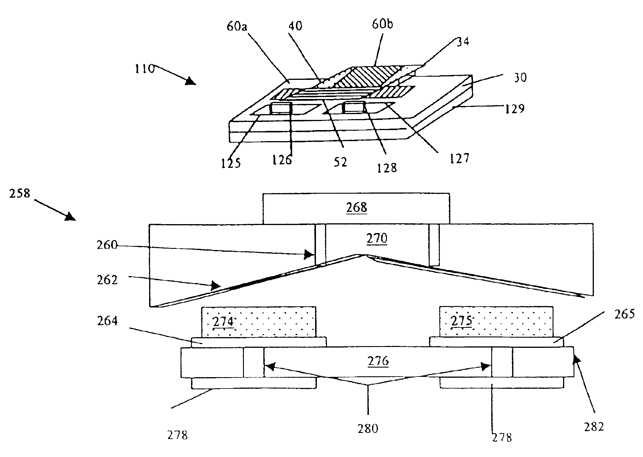
With such an arrangement inserting liquid metal contacts into a MEM micro-relay is accomplished by taking advantage of the capillary flow of liquid metals and inserting the liquid metal after the micro-relay is fully fabricated. This method allows a MEM contact structure to be co-fabricated with the MEM actuator.
With such an arrangement inserting liquid metal contacts into a MEM micro-relay can be is accomplished by taking advantage of the capillary flow of liquid metals and inserting the liquid metal after the micro-relay is fully fabricated. This method allows a MEM contact structure to be co-fabricated with the MEM actuator.
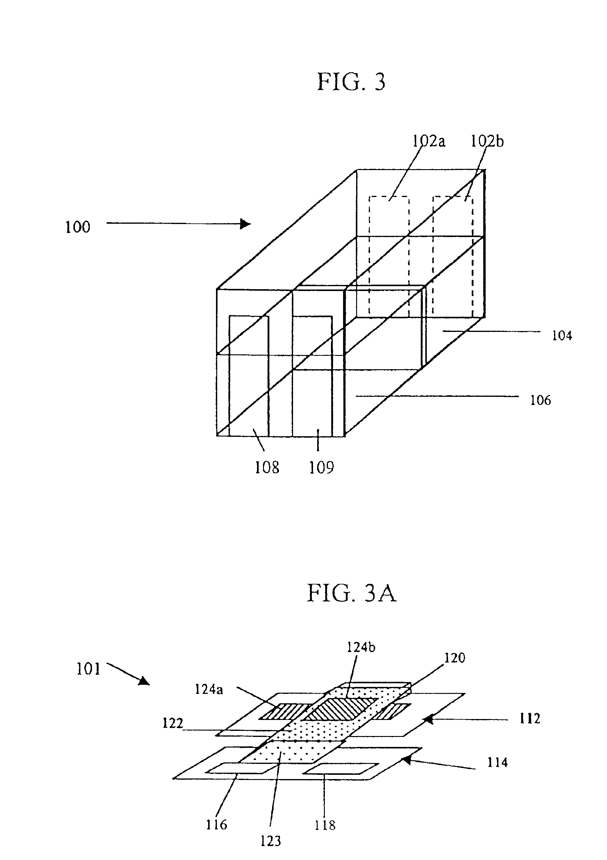
With such a fabrication technique, the liquid metal contacts can receive liquid metal from an external source supplied through the vias. In addition a larger quantity of liquid metal can form liquid metal contacts which can form a physical electrical connection without a requirement for a conductive metal shorting bar. The contacts fabricated with the inventive technique have a longer life, can carry higher currents, and can handle higher voltage signals than typical contacts used in MEM relays.
In accordance with yet another aspect of the present invention, a MEM relay includes a separately fabricated contact substrate having at least two liquid metal contacts. The control substrate is bonded to an actuator substrate. With such an arrangement the contact system is fabricated separately from the actuation system, and then the two assemblies are bonded together allowing the use of liquid metal inserted on wettable metal contact surfaces or the use of liquid metal contacts which can be placed in electrical and mechanical contact. The liquid metal wetted metal contacts and the liquid metal contacts provide a long life, high current, and high voltage contacts for MEM relays.

Problems solved by technology

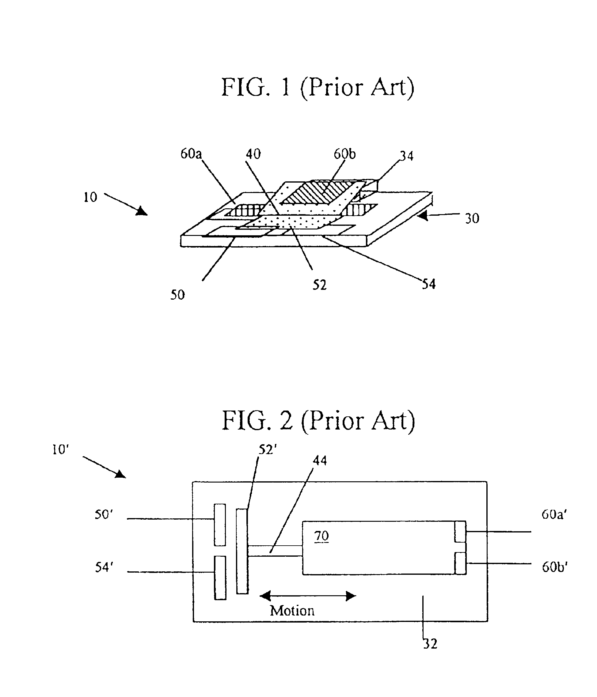
Although the physical size of conventional relays makes the concept of heating the contacts or the whole relay impractical, the microscopic nature of MEM micro-relay contacts as compared to conventional relay contacts makes it feasible to heat the contact region (or the whole MEM micro-relay) in order to obtain a liquid contact operation.

Method used


Image

  • Microelectromechanical micro-relay with liquid metal contacts
  • Microelectromechanical micro-relay with liquid metal contacts
  • Microelectromechanical micro-relay with liquid metal contacts

Examples


Embodiment Construction

Before proceeding with a detailed discussion of the instant invention, some introductory concepts and terminology are explained. The term “liquid metal contact” refers to an electric contact whose mating surface during the conduction of electric current consists of a molten metal or molten metal alloy. The liquid metal contact (molten metal) will be retained (held in place) by a solid (non-molten) structure. The solid structure may be wettable so that it will retain a layer of a liquid metal, for example mercury. The term “liquid metal contact” can also refer to a quantity of liquid metal which forms a structure, for example a droplet, which is held in place by surface tension on a metal surface of a MEM device or a retaining structure to control the position of the liquid metal. The terms switch and relay are used interchangeably.

MEM devices are typically built using substrates compatible with current integrated circuit fabrication, although some of the electronic switch or relay s...


PUM


Abstract

A MEM relay includes an actuator, a shorting bar disposed on the actuator, a contact substrate, and a plurality of liquid metal contacts are disposed on the contact substrate such that the plurality of liquid metal contacts are placed in electrical communication when the MEM relay is in a closed state. Further, the MEM relay includes a heater disposed on said contact substrate wherein said heater is in thermal communication with the plurality of liquid metal contacts. The contact substrate can additionally include a plurality of wettable metal contacts disposed on the contact substrate wherein each of the plurality of wettable metal contacts is proximate to each of the plurality of liquid metal contacts and each of the wettable metal contacts is in electrical communication with each of the plurality of liquid metal contacts.

Description

FIELD OF THE INVENTIONThe present invention relates to electrical and electronic circuits and components. More specifically, the present invention relates to micro-electromechanical (MEM) relays with liquid metal contacts.BACKGROUND OF THE INVENTIONA MEM switch is a switch operated by an electrostatic charge, thermal, piezoelectric or other actuation mechanisms and manufactured using micro-electromechanical fabrication techniques. A MEM switch may control electrical, mechanical, or optical signal flow. Conventional MEM switches are usually single pole, single throw (SPST) configurations having a rest state that is normally open. In a switch having an electrostatic actuator, application of an electrostatic charge to the control electrode (or opposite polarity electrostatic charges to a two-electrode configuration) will create an attractive electrostatic force (‘pull’) on the switch causing the switch to close. The switch opens by removal of the electrostatic charge on the control ele...

Claims


Application Information

Patent Timeline
IPC IPC(8): H01H1/06H01H1/62H01H1/08H01H1/00H01H50/00H01H59/00B81B3/00H01H1/04
CPCH01H1/08H01H50/005H01H1/62H01H1/0036H01H2029/008H01H59/0009H01H59/00
Inventor STREETER, ROBERT D.MCMILLAN, LEE A.BERGSTEDT, RODERICK G.
Owner RAYTHEON CO
Learn More