
Method and apparatus for detecting anomalous measurements in a satellite navigation receiver

a satellite navigation and anomalous measurement technology, applied in the field of satellite navigation receivers, can solve the problems of ambiguity resolution, the difference in the phase delay of a carrier signal received by the base and rover receivers may substantially exceed one cycle, and it is not possible to measure the integer number of cycles from the incoming satellite signal, so as to increase the accuracy of a navigation task

Active Publication Date: 2005-03-01
TOPCON GPS
View PDF8 Cites 56 Cited by
  • Summary
  • Abstract
  • Description
  • Claims
  • Application Information

AI Technical Summary

Benefits of technology

Upon identification of an anomalous phase measurement, the information about the anomalous phase measurement may be used by a satellite navigation receiver in order to increase the accuracy of a navigation task. In addition, a cycle slip estimate for a channel determined to have an anomalous phase measurement may be computed, and such cycle slip estimate may also be used in the navigation task.

Problems solved by technology

The practical implementation of those advantages, which might otherwise be guaranteed by the measurement of the carrier phases, runs into the problem of ambiguity resolution for phase measurements.
Therefore, the difference in the phase delays of a carrier signal received by the Base and Rover receivers may substantially exceed one cycle.
Second, it is not possible to measure the integer number of cycles from the incoming satellite signals; one can only measure the fractional part.
In most cases the Rover receiver operates in a complicated environment in which various external influences cause measurement errors.
For example, external signals may interfere with the satellite signals, and structures and terrain may result in multipath errors.
Abnormal errors are large systematic errors which may prevent the system from calculating an accurate location.
More often, they are the result of severe exposure of the receiver.
For example, strong reflected signals that interfere with the direct satellite signal would cause an abnormal error.
Similarly, extreme radio interference may also result in abnormal errors.
Partial or complete shading of the Rover receiver may also result in errors due to radio wave diffraction.
If the shading is partial and minor, the measurement error may be minimal.
However, if a satellite is completely shaded (i.e., blocked), all that remains is the multipath signal.
As a result, tracking in the channel is interrupted and the measured phase is lost resulting in an abnormal error.
Dynamic effects on the receiver (i.e., certain motion of the Rover) may also cause abnormal errors.
One specific type of abnormal error is a PLL cycle slip which is a cycle slip in the PLL circuits which are tracking the satellite carrier signal.
When the duration is long enough, tracking is lost.

Method used


Image

  • Method and apparatus for detecting anomalous measurements in a satellite navigation receiver
  • Method and apparatus for detecting anomalous measurements in a satellite navigation receiver
  • Method and apparatus for detecting anomalous measurements in a satellite navigation receiver

Examples


first embodiment

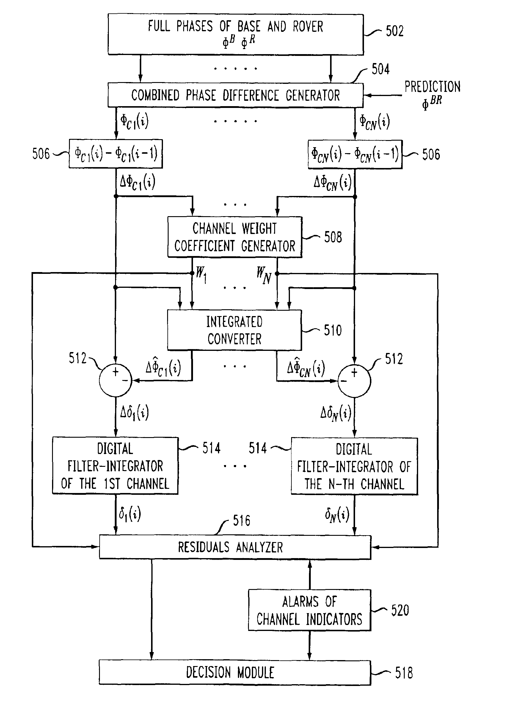
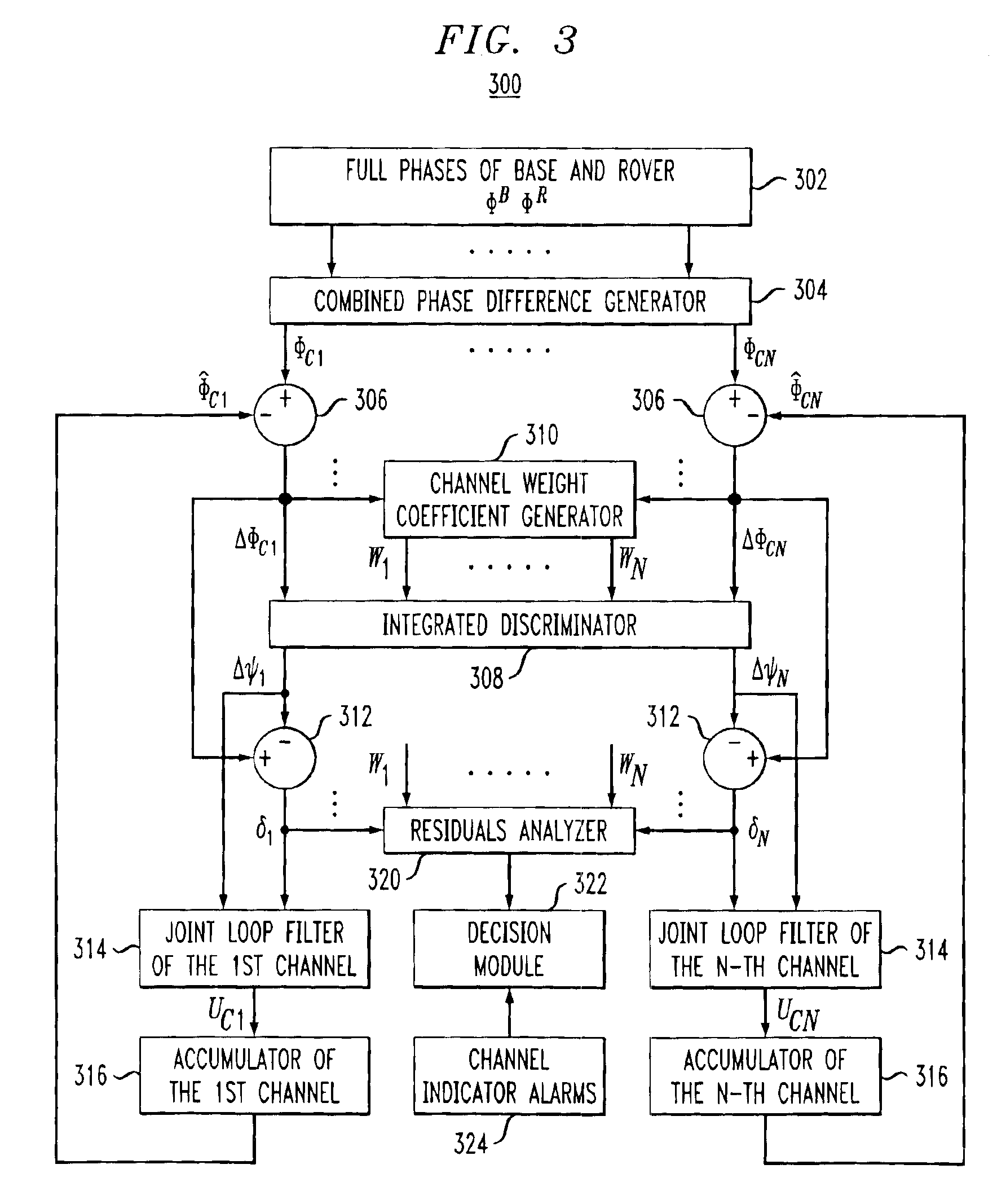
FIG. 3 shows a functional block diagram of an anomaly indicator module 300 which utilizes a feedback loop. FIG. 3 only shows details for channels 1 and N since the processing of all channels is the same. Function blocks which are common to all channels are also shown. It is noted that the functional block diagrams (e.g., FIGS. 2-6) herein are meant to describe high level functioning of a unit. One skilled in the art would readily recognize that some of the blocks represent input parameters, others represent output parameters, while others represent some function or operation. The functions and operations may be performed by hardware circuits, software instructions executing on a processor, or some combination of hardware and software. Given the description herein, those skilled in the art would be able to implement the described functionality using various combinations of hardware and software. As such, implementation details of the functions described herein will not be described i...

second embodiment

the residual analyzer is based upon verifying the so-called criterion χ2 in which a weighted sum of residual squares is compared to the threshold. In this embodiment, the weighted sum is calculated according to equation (11): χ2=∑j=1n⁢wj⁡(δj)2,(11)

where wj is the weight coefficient of the j-th channel as shown above, n is the number of remaining channels (i.e., n will be equal to N at the outset, and may be reduced as a result of eliminating channels from the phase mismatch calculation as described above). If the phase mismatches ΔΦcj are normal random values independent in different channels, then the weighted sum of residual squares χ2 has distribution according to χ2-law with (n−2) degree of freedom. The corresponding distribution (χ2-law) may be determined by well known techniques. Based on the probability distribution law one can determine the threshold πz to which the value χ2 is to be compared to result in a relatively small acceptable probability of false alarm. For example,...

third embodiment

the residual analyzer is also based on criteria χ2, but locates the channel with the anomalous measurement in a different way. Once the threshold has been exceeded, it is assumed that an anomalous measurement exists in one channel only and the channels are eliminated one by one. However, upon eliminating a particular channel and recalculating χ2, if the threshold remains exceeded using the remaining n=N−1 channels, then the particular channel is returned to the set of channels used in the calculation of χ2 and a second channel is eliminated. Again, χ2 is recalculated with the remaining n=N−1 channels. A first search continues in this manner until either the one channel having the anomalous measurement is found, or after eliminating all channels and the threshold continuing to be exceeded, it is determined that more than one channel has an anomalous measurement. In the latter case, a second search is initiated now eliminating channel pairs and computing χ2 using n=N−2 channels. A sec...


PUM


Abstract

A method and apparatus for detecting and correcting anomalous measurements in a satellite navigation receiver is disclosed. Anomalous measurements are detected using the redundancy of observed satellite signals, or by analyzing the relationship between phase measurements at two frequencies when using dual frequency receivers. Upon determination that an anomalous measurement exists, the particular channel on which the anomalous measurement has occurred is determined. In addition, the extent of the anomalous measurement is estimated to produce an estimated error value. This information may then be used by the satellite navigation receiver in order to increase the accuracy of a navigation task.

Description

BACKGROUND OF THE INVENTIONThis invention relates generally to satellite navigation receivers and more particularly to the detection and correction of anomalous measurements in a satellite navigation receiver.Satellite navigation systems, such as GPS (USA) and GLONASS (Russia), are well known in the art and are intended for highly accurate self-positioning of users possessing special navigation receivers. A navigation receiver receives and processes radio signals transmitted by satellites located within line-of-sight distance of the receivers. The satellite signals comprise carrier signals that are modulated by pseudo-random binary codes. The receiver measures the time delay of the received signal relative to a local reference clock or oscillator. These measurements enable the receiver to determine the so-called pseudo-ranges between the receiver and the satellites. The pseudo-ranges are different from the ranges (distances) between the receiver and the satellites due to various noi...

Claims


Application Information

Patent Timeline
IPC IPC(8): H04B7/185G01S1/00G01S19/05G01S5/14G01S19/11G01S19/21G01S19/29G01S19/46
CPCG01S19/23G01S19/41G01S19/32
Inventor ZHODZISHSKY, MARK I.VEITSEL, VICTOR A.NARIZHNY, ANDREY V.
Owner TOPCON GPS
Learn More