
Moisture-sensitive device protection system

Inactive Publication Date: 2005-03-01
DELPHI TECH INC
View PDF11 Cites 10 Cited by
  • Summary
  • Abstract
  • Description
  • Claims
  • Application Information

AI Technical Summary

Benefits of technology

Another advantage of the present invention is that it is versatile in application. It may be applied to multiple style integrated circuits and integrated circuit housings and may be applied using multiple methods.
is that it is versatile in application. It may be applied to multiple style integrated circuits and integrated circuit housings and may be applied using multiple methods.
Furthermore, the present invention provides multiple methods of preventing moisture absorption of an integrated circuit mold that consumes a minimal amount of time and is cost effective.

Problems solved by technology

During production and manufacturing of these systems, ICs may remain unused (e.s. in inventory) for extended periods of time, where they can be exposed to environmental conditions, such as, humidity and moisture.
Of course, exposure to the elements, such as moisture, may also occur during other production downtime events, which are experienced in conventional manufacturing and assembly operations.
Once the bag is opened to begin manufacturing, the components have a limited useful life.
ICs that have been exposed for extended periods of time to levels of moisture typically found in air at most production and manufacturing facilities, are vulnerable to internal damage when processed in a reflow oven.
This vulnerability requires special handling methods that increase manufacturing costs.
When the IC is baked, due to the moisture level of the molding compound, delamination of mold from the silicon device can occur, with consequent breaking of wire bonds.
The broken wire bonds cause intermittence during post assembly operating use of the IC.
Although ICs are tested upon completion of assembly before being used as intended, the delamination may be undetectable, since the silicon device wire bonds may be resting on or touching silicon device contacts even though a wire bond no longer exists.
A disadvantage with the dry box is that the moisture that previously entered the IC, remains in the IC, which may cause operating intermittence.
Obviously, this baking is time consuming, not cost effective, and can cause oxydation of solder coating on IC leads, degrading the ability to have a solder joint formed to the IC.
As another method, the ICs can be reinserted into moisture barrier bags, during downtime, although is also time consuming and requires a supply of moisture barrier bags and desiccant material, as well as a sealing apparatus.

Method used


Image

  • Moisture-sensitive device protection system
  • Moisture-sensitive device protection system
  • Moisture-sensitive device protection system

Examples


Embodiment Construction

In each of the following figures, the same reference numerals are used to refer to the same components. While the present invention is described with respect to methods and apparatuses for preventing moisture absorption by an integrated circuit, the present invention may be applied in various manufacturing and production processes. It is also understood that the present invention may be applied in assembly of various systems including: electronic systems, control systems, computer-based systems, logic-based systems, and other systems known in the art.

In the following description, various operating parameters and components are described for one constructed embodiment. These specific parameters and components are included as examples and are not meant to be limiting.

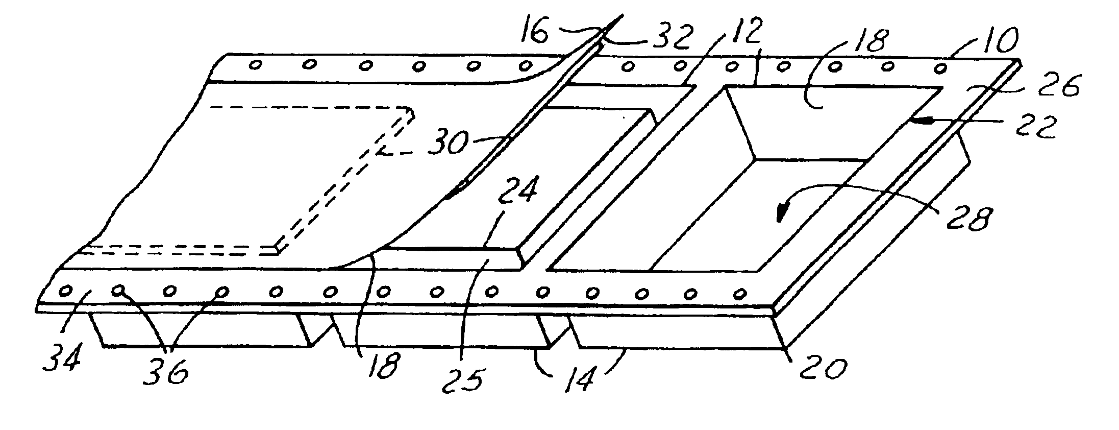
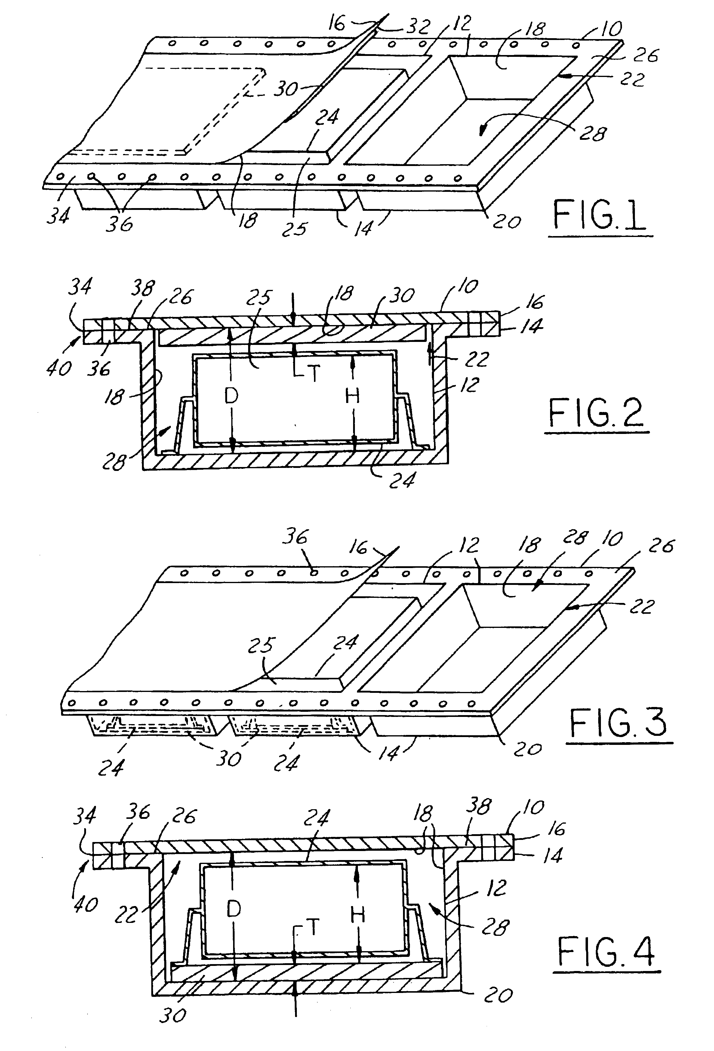
Referring now to FIGS. 1-4, perspective views and cross-sectional views of integrated circuit moisture resistant apparatuses 10, are shown, in accordance with an embodiment of the present invention. The moisture resistant...


PUM


Abstract

Integrated circuit moisture resistant apparatuses (10) are provided for preventing moisture absorption by an integrated circuit (24). The moisture resistant apparatuses include at least one integrated circuit housing (12) that has a plurality of inner walls (18), which form at least one inner cavity (28). A desiccant body (30) is coupled to at least a portion of the plurality of inner walls (18) and absorbs moisture within the inner cavity (28). A method for performing the same is provided. Also, a manufacturing method of preventing moisture absorption by the integrated circuit (24) is provided.

Description

TECHNICAL FIELDThe present invention relates generally to integrated circuits, and more particularly, to apparatuses and methods of extending the life of moisture-sensitive devices.BACKGROUND OF THE INVENTIONIntegrated circuits (ICs) are commonly used in various electronic systems, including computer-based systems, logic based systems, control systems, and other systems known in the art. During production and manufacturing of these systems, ICs may remain unused (e.s. in inventory) for extended periods of time, where they can be exposed to environmental conditions, such as, humidity and moisture. The moisture typically can be in the form of water vapor in air. Exposure to moisture typically can occur during production downtime, for example, during production “change-overs” or during small quantity production of an electronic system, where continuous production is not required. Of course, exposure to the elements, such as moisture, may also occur during other production downtime even...

Claims


Application Information

Patent Timeline
IPC IPC(8): H01L23/16H01L23/26
CPCH01L23/26H01L2924/0002H01L2924/00
Inventor BAAR, JAMES CBLAZIER, MICHAEL W
Owner DELPHI TECH INC
Learn More