
Water pumping station with an integral valve vault

a valve vault and water pumping station technology, applied in the field of waste or storm water pumping station and system, can solve the problems of differential settlement still occurring, piping breaking or leakage, and serious deficiencies in prior art pumping system, and achieves the effects of reducing the footprint, reducing the risk of differential settlement, and reducing the cost of operation

Active Publication Date: 2014-11-06
OLDCASTLE PRECAST
View PDF8 Cites 30 Cited by
  • Summary
  • Abstract
  • Description
  • Claims
  • Application Information

AI Technical Summary

Benefits of technology

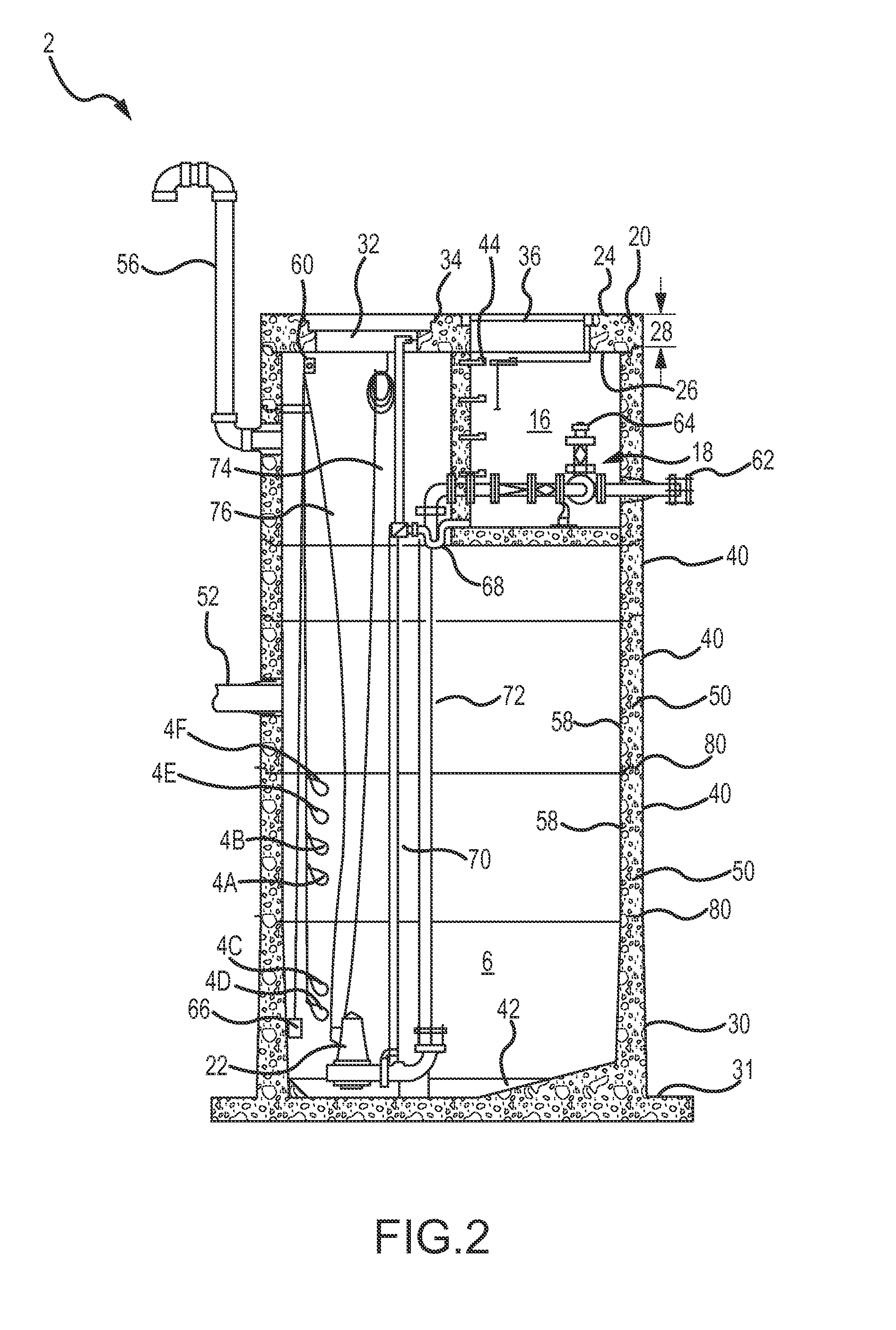
The present invention provides a new and useful water pumping station and system with a single-structure enclosure having an integral valve vault. This system has several technical benefits, including being simpler in fabrication and installation, having a smaller footprint, eliminating differential settlement, requiring a single tier excavation rather than a two-tier excavation, reducing the size and depth of the excavation required, and improving safety. The system also has a higher storage capacity by combining the valve vault chamber and the wet well collection chamber into a single-unit of uniform length and locating the valve vault chamber in the unusable space of the wet well. These technical effects make the new system more versatile and functional than previous devices.

Problems solved by technology

While pumping stations have long been used to raise waste or storm water to higher elevations within a management and conveyance system, there are serious deficiencies and inadequacies with the prior art pumping systems.
A significant problem with having two separate structures is that each structure will settle at a different rate and depth, commonly referred to as differential settlement.
When differential settlement occurs, the piping between the two structures is compromised resulting in breaks and leaks that require excavating the area around and between the structures to repair the damage and stop the leaks.
Even after a break has been repaired, there is still the possibility that the piping will break or leak again in the future.
While the problem of separate water pump station structures can be somewhat addressed by fixedly connecting the two separate structures together with fasteners such as bolts, as was done in U.S. Pat. No. 7,150,290 to Smith (“Smith”), which is herein incorporated by reference in its entirety, the problem of differential settlement can still occur due to the different sizes and depths of the two structures.
One other deficiency with the Smith structure is that the valve vault chamber is approximately one half the depth of the collection chamber, which results in space beneath the valve vault chamber that is filled with soil when it could be used to increase the storage capacity of the collection chamber.
Either installation may result in differential settlement, which may cause the entire structure to tilt out of plumb.

Method used


Image

  • Water pumping station with an integral valve vault
  • Water pumping station with an integral valve vault
  • Water pumping station with an integral valve vault

Examples


Embodiment Construction

[0073]Although the following text sets forth a detailed description of numerous different embodiments, it should be understood that the legal scope of the description is defined by the words of the claims set forth at the end of this disclosure. The detailed description is to be construed as exemplary only and does not describe every possible embodiment since describing every possible embodiment would be impractical, if not impossible. Numerous alternative embodiments could be implemented, using either current technology or technology developed after the filing date of this patent, which would still fall within the scope of the claims. Also note that the scale for each figure is different. Thus, the scale for FIG. 1 is different from the scale of FIG. 2, etc.

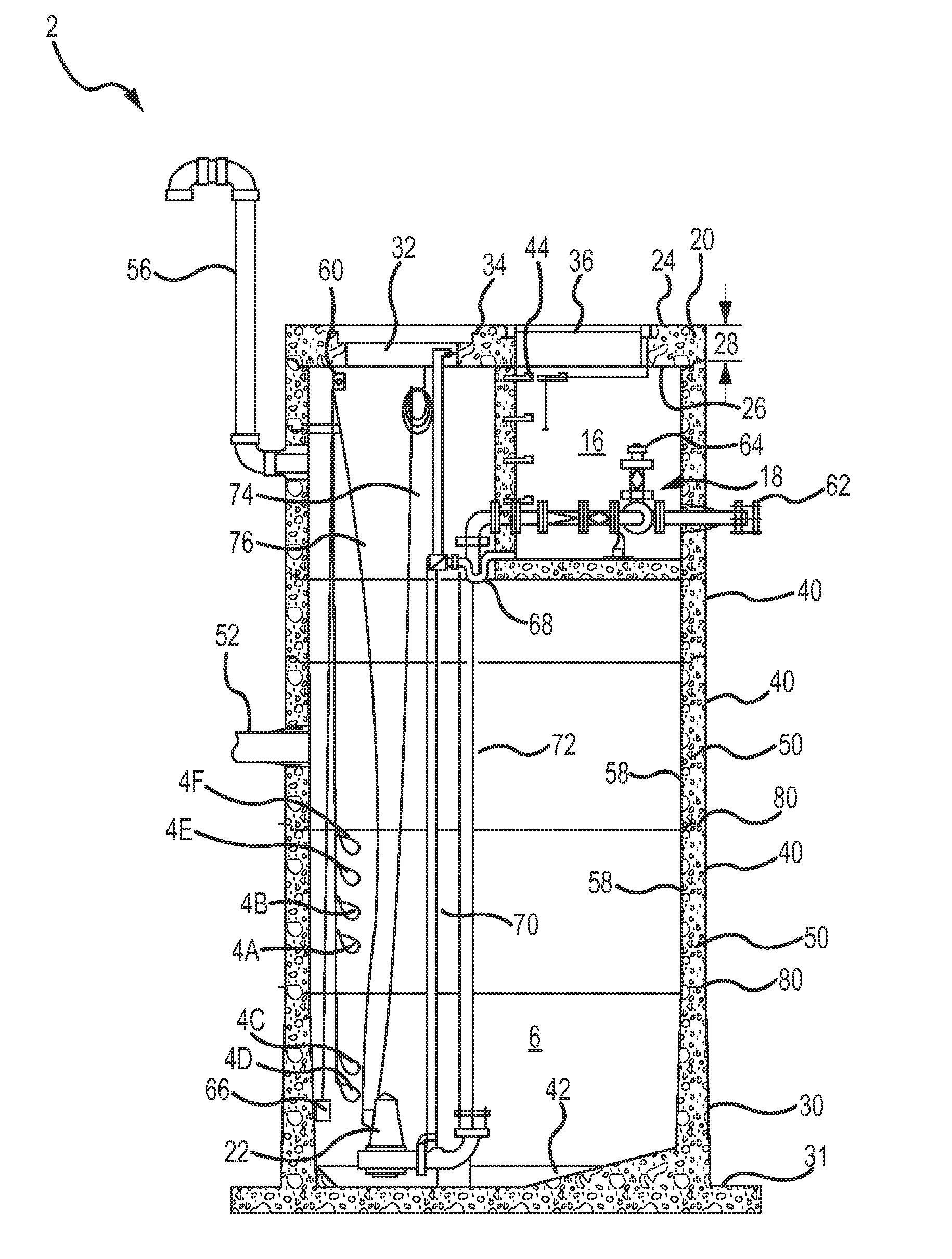
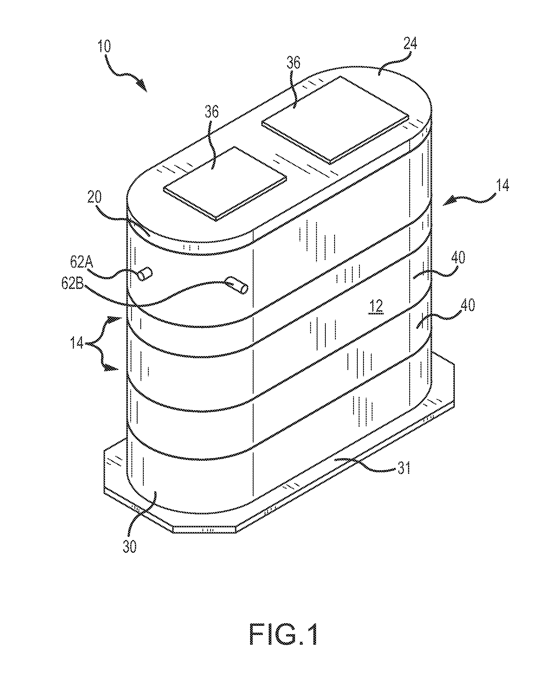
[0074]FIG. 1 shows one embodiment of a pump station body. In the embodiment shown, the pump station body 10 comprises a top slab 20, a top surface 24, outlets 62A, 62B, two access covers 36, risers 40, a base 30, and a base slab...


PUM

PropertyMeasurementUnit
compressive strengthaaaaaaaaaa
depthaaaaaaaaaa
heightaaaaaaaaaa

Abstract

A waste or storm water pumping station and system used to pump water from a lower elevation to a higher elevation during the process of moving or managing the water is disclosed herein. The pumping station has a wet well collection chamber with a sloped floor and an integral valve vault chamber cast within the pump station body, which results in increased storage capacity in the wet well chamber for pump station components. Additionally, the pumping station may be installed as a single unit of equal depth to eliminate differential settlement and multiple or uneven excavations.

Description

RELATED APPLICATION[0001]This application claims priority from U.S. Provisional Patent Application Ser. No. 61 / 818,700, filed May 2, 2013, entitled “Water Pumping Station Having Integral Valve Vault,” the entire disclosure of which is incorporated by reference herein.FIELD OF THE INVENTION[0002]Embodiments of the present invention relate generally to waste and storm water management, and more specifically to an improved waste or storm water pumping station and system.BACKGROUND OF THE INVENTION[0003]A variety of gravity-based systems have long been used to move waste and / or storm water through management and conveyance systems and on to treatment or storage systems. These management and conveyance systems often require pumping stations to lift the water from a lower elevation to a higher elevation such that gravity can be used to move the waste and / or storm water through the system. Lifting pump stations and systems typically have two major components: (1) a collection or pumping co...

Claims


Application Information

Patent Timeline
Patent Type & Authority Applications(United States)
IPC IPC(8): E03F5/22
CPCE03F5/22Y10T29/49229Y10T137/6991Y10T137/6995
Inventor PASCO, KEN
Owner OLDCASTLE PRECAST
Learn More