
Storage virtualization system and methods

a virtualization system and storage technology, applied in the field of storage virtualization system and methods, can solve the problems of large management, maintenance, cost, and general inability of the operating system to perceive the storage device as anything but real disks, and the expansion of the customer's storage needs is often expensive and laborious

Inactive Publication Date: 2005-02-15
EMC IP HLDG CO LLC
View PDF14 Cites 177 Cited by
  • Summary
  • Abstract
  • Description
  • Claims
  • Application Information

AI Technical Summary

Benefits of technology

The present invention provides a storage virtualization system that allows customers to manage storage as a utility, rather than as isolated islands. The system presents a demand mapped virtual disk image to the end-consumer, which is a very large image that isolates the user from volume resizing issues and allows easy consumption. The system dynamically maps addresses between the virtual disk address and physical block addresses for a storage system in response to a write operation requested by a host system. The method includes determining if memory space in the storage system has been allocated for the virtual memory address and completing the write operation to the allocated memory space. The invention offers many advantages over prior systems, including reduced overhead, lower costs, and new business models.

Problems solved by technology

In fact, it is generally impossible for an operating system to perceive them as anything but real disks.
Storage Service Providers (SSPs) are developing large customer bases, potentially in the millions, so manageability, maintenance, and cost are major concerns.
Because it takes time to acquire, physically configure and / or re-partition disks, and to copy data to the new disks when storage needs change, expanding customer storage needs are often expensive and labor intensive.
Additionally, customer separation, which ensures customer data remains secure and completely separate from the data of other storage customers, adds to the maintenance burden.
With traditional “separation” mechanisms such as Logical Unit Number (LUN) masking, physical isolation, and separation of management, “customer separation” can quickly become unwieldy and impractical—creating a maintenance and support nightmare.

Method used


Image

  • Storage virtualization system and methods
  • Storage virtualization system and methods
  • Storage virtualization system and methods

Examples


Embodiment Construction

nying drawings. In the drawings, like reference numbers indicate identical or functionally similar elements.

BRIEF DESCRIPTION OF THE DRAWINGS

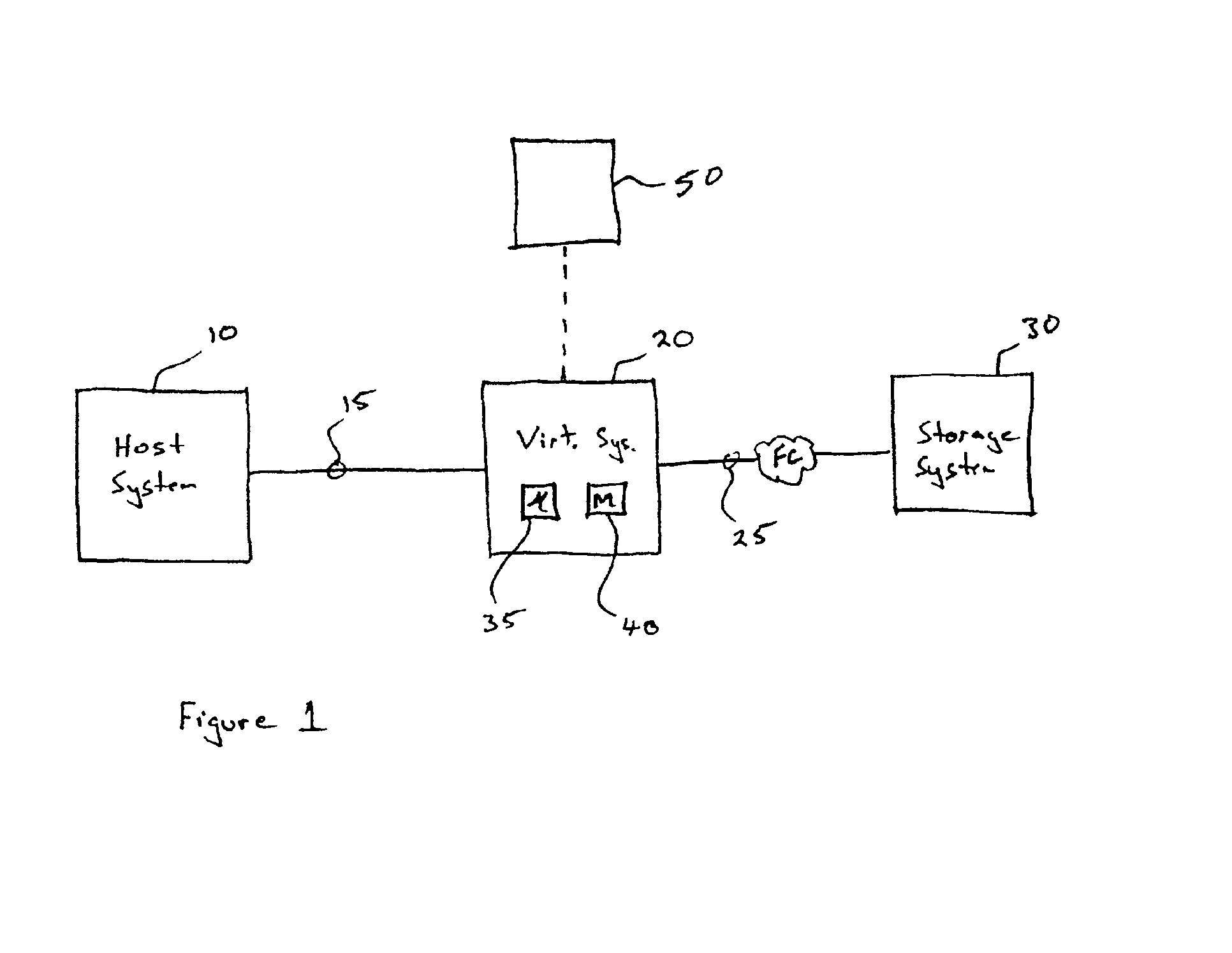
[0029]FIG. 1 illustrates an example network architecture including the storage virtualization system of the present invention;

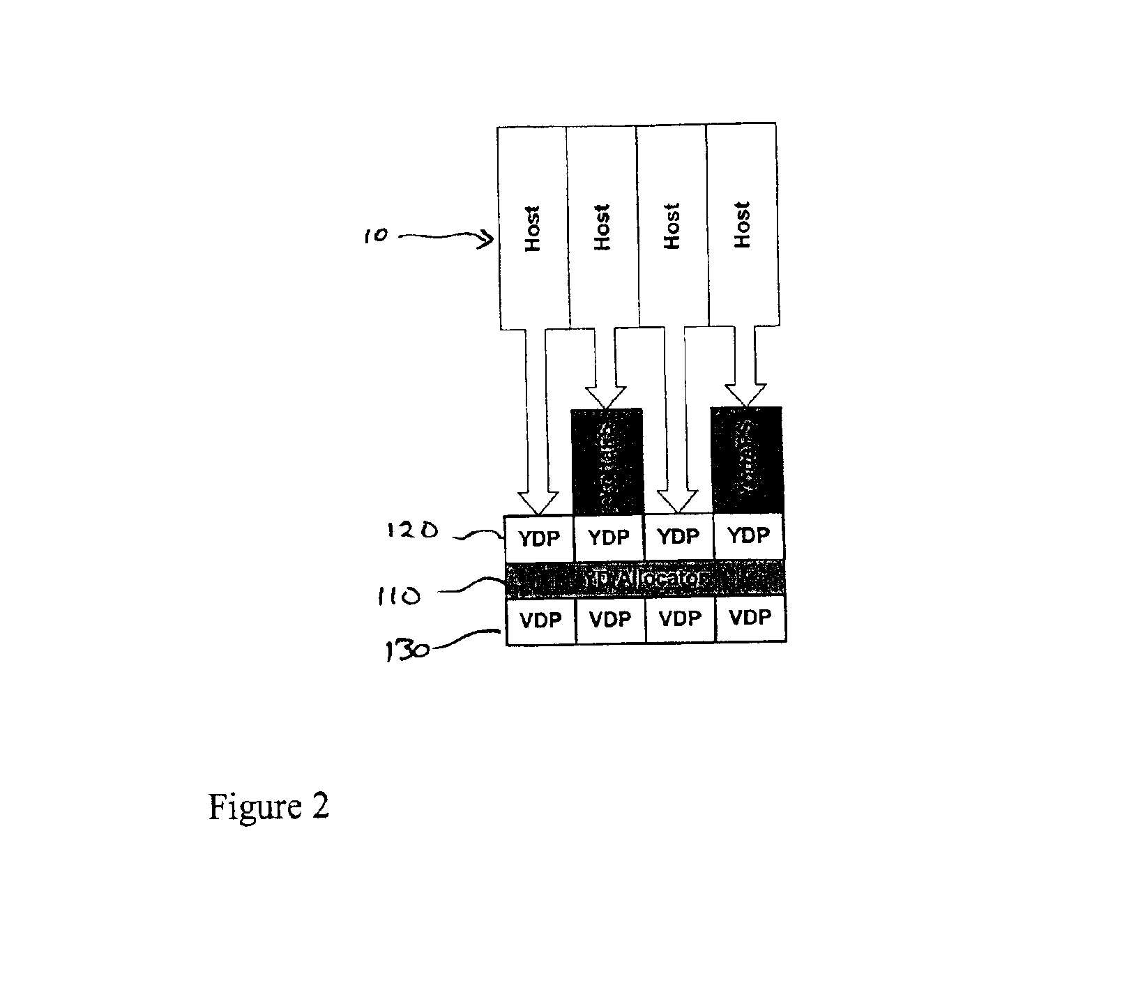
[0030]FIG. 2 illustrates an implementation of disk images according to one embodiment that includes a disk image layer in front of the VDP layer;

[0031]FIG. 3 illustrates a software stack according to one embodiment of the present invention, wherein controller cards implement the virtualization system of the present invention;

[0032]FIG. 4 shows two subsequent snapshots being made from the disk images in FIG. 5b according to an embodiment of the present invention; and

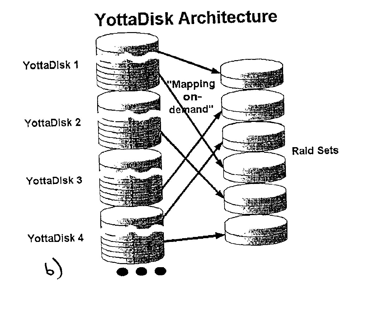
[0033]FIGS. 5a and 5b illustrate a traditional architecture and a demand-mapped virtual disk architecture according to an embodiment of the present invention, respectively.

DETAILED DESCRIPTION OF THE INVENTION

[0034]The present invention provides a virtualizati...


PUM


Abstract

Storage virtualization systems and methods that allow customers to manage storage as a utility rather than as islands of storage which are independent of each other. A demand mapped virtual disk image of up to an arbitrarily large size is presented to a host system. The virtualization system allocates physical storage from a storage pool dynamically in response to host I / O requests, e.g., SCSI I / O requests, allowing for the amortization of storage resources through a disk subsystem while maintaining coherency amongst I / O RAID traffic. In one embodiment, the virtualization functionality is implemented in a controller device, such as a controller card residing in a switch device or other network device, coupled to a storage system on a storage area network (SAN). The resulting virtual disk image that is observed by the host computer is larger than the amount of physical storage actually consumed.

Description

CROSS-REFERENCES TO RELATED APPLICATIONS[0002]This application claims the benefit of U.S. patent application Ser. No. 60 / 261,140, filed Jan. 11, 2001, entitled, “Storage Virtualization System & Methods,” the disclosure of which is hereby incorporated by reference in its entirety.BACKGROUND OF THE INVENTION[0003]The present invention relates generally to systems and methods for implementating storage virtualization in a data storage network, and more specifically to systems and methods of utilizing multiple storage devices in a network and managing the storage devices as a single entity enabling storage to be utilized as a utility.[0004]The role of data is changing. Its true value to a business and a computer system is being recognized. This change is driving the return of storage architecture to a data center model. In this model, disk storage is the nucleus of the computing system and is thereby centrally located in a controlled environment. This approach significantly lowers the c...

Claims


Application Information

Patent Timeline
Patent Type & Authority Patents(United States)
IPC IPC(8): G06F12/08G06F3/06
CPCG06F3/0605G06F3/0608G06F12/08G06F3/0665G06F3/067G06F3/0631
Inventor KARPOFF, WAYNELAKE, BRIAN
Owner EMC IP HLDG CO LLC
Learn More