Image fixing method

a technology of infrared light and fixing method, which is applied in the field of image formation method, can solve the problems of not solving all the problems described above, affecting the chroma and hue of a color image, and adding a small amount of infrared light absorbent material does not sufficiently improve the fusion properties of the binder resin, etc., and achieves low irradiation power, efficient transmission, and easy to achieve

Inactive Publication Date: 2005-02-08
FUJIFILM BUSINESS INNOVATION CORP
View PDF8 Cites 0 Cited by
  • Summary
  • Abstract
  • Description
  • Claims
  • Application Information

AI Technical Summary

Benefits of technology

According to findings by the inventors of the present invention, et al., an image formation with a practically acceptable color reproduction capability is obtained by setting up the PAS strength value of the toner forming the n-th layer, which is located closest to the luminous source, higher than the PAS strength value of the toner forming any other layer, when forming the laminated toner layer consisting of the first layer at the bottom and immediately above the recording medium through the n-th layer. This configuration can be built simply and economically.
For the color toner that contains two or more infrared light absorbents, each absorbent having a different absorption spectrum, absorption efficiency in the 800-2000 nm wavelength range is enhanced, resulting in a higher PAS strength value, further resulting in a satisfactory fixing of an image. An infrared absorbent typically has one absorption peak in a specific wavelength range. Increasing an amount of only one kind of the infrared absorbent that absorbs only a part of the 800-2000 nm range is not an efficient method. What is worse is that the increased amount of the infrared absorbent deteriorates the chroma of the image, and the like, as discussed above. The color toner, according to the present invention, containing two or more infrared absorbents that have absorption peaks in different areas within the 800-2000 nm range realizes a higher efficiency in using the energy irradiated, while alleviating the image quality deterioration caused by using a large amount of one absorbent.

Problems solved by technology

However, the conventional technologies, which, in essence, simply add the infrared light absorbent, have not solved all the problems described above.
Specifically, adding a small amount of the infrared light absorbent material does not sufficiently improve the fusion properties of the binder resin.
That is, if a large amount of these materials is used, chroma and hue of a color image is adversely affected.
As mentioned above, the flashlight method of the conventional technology still requires a large amount of radiant energy in order to firmly fix the color toner.
The above problem of needing the large amount of radiant energy becomes a bigger problem in multi-color and full-color image formation, when a “sequential developments and one-time fixing” method is used, wherein a plurality of toner powder image layers are laminated, and then the laminated layers are fixed by one shot.
In addition, even if the radiant energy is simply increased for fixing the laminated layer, it is difficult to obtain firm toner fixing.
It is because not only the total amount of the toner to be fused by irradiation of light is large, but also the flashing light is absorbed by upper toner layers, and lower layers that are closer to the recording medium, and therefore, more relevant to the fixing properties, do not receive sufficient energy for fusing.
Therefore, a problem is that an image formation apparatus tends to be large-sized, expensive, and the radiant energy absorption efficiency therein falls, being incapable of meeting recent requirements for higher speed in forming an image.

Method used


Image

  • Image fixing method
  • Image fixing method
  • Image fixing method

Examples


Embodiment Construction

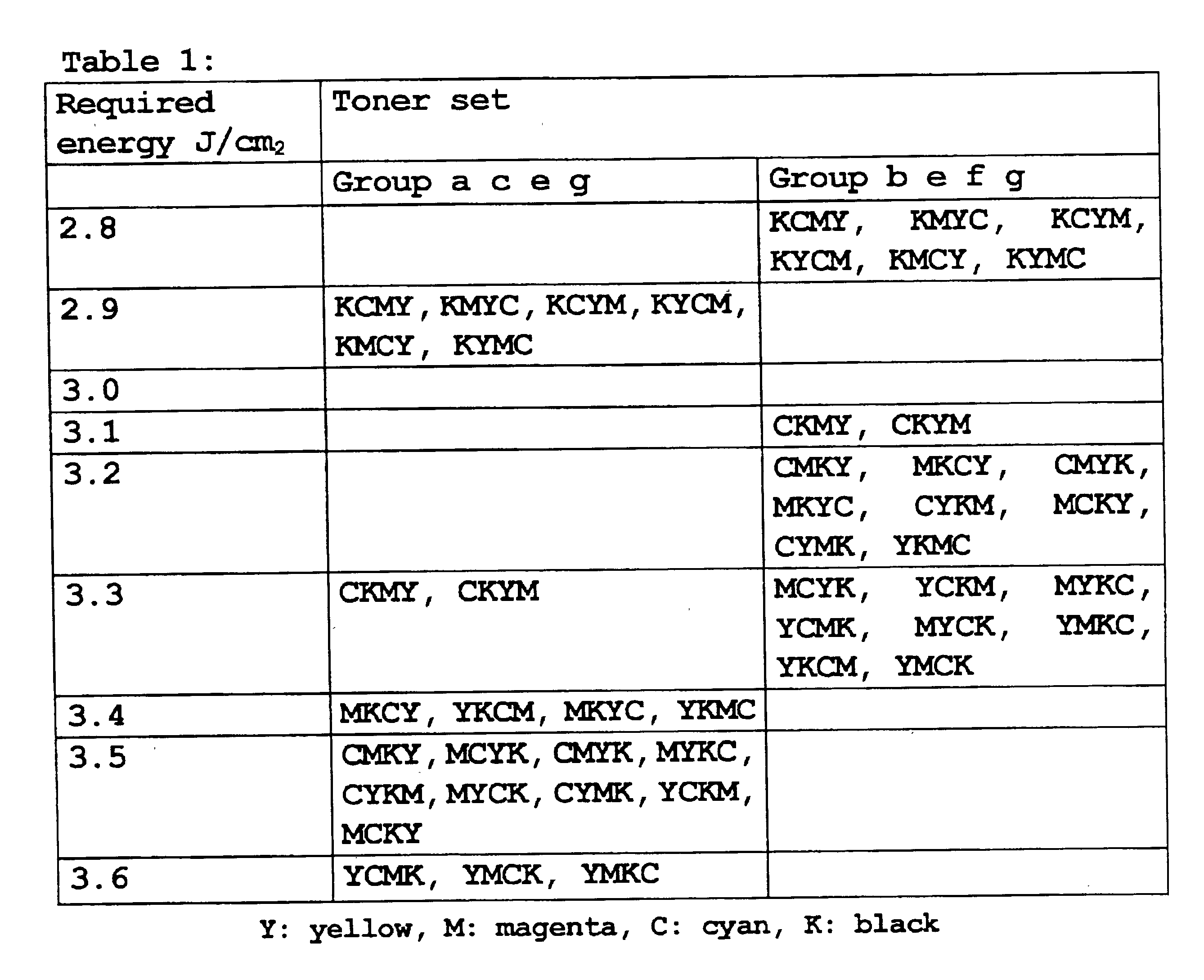
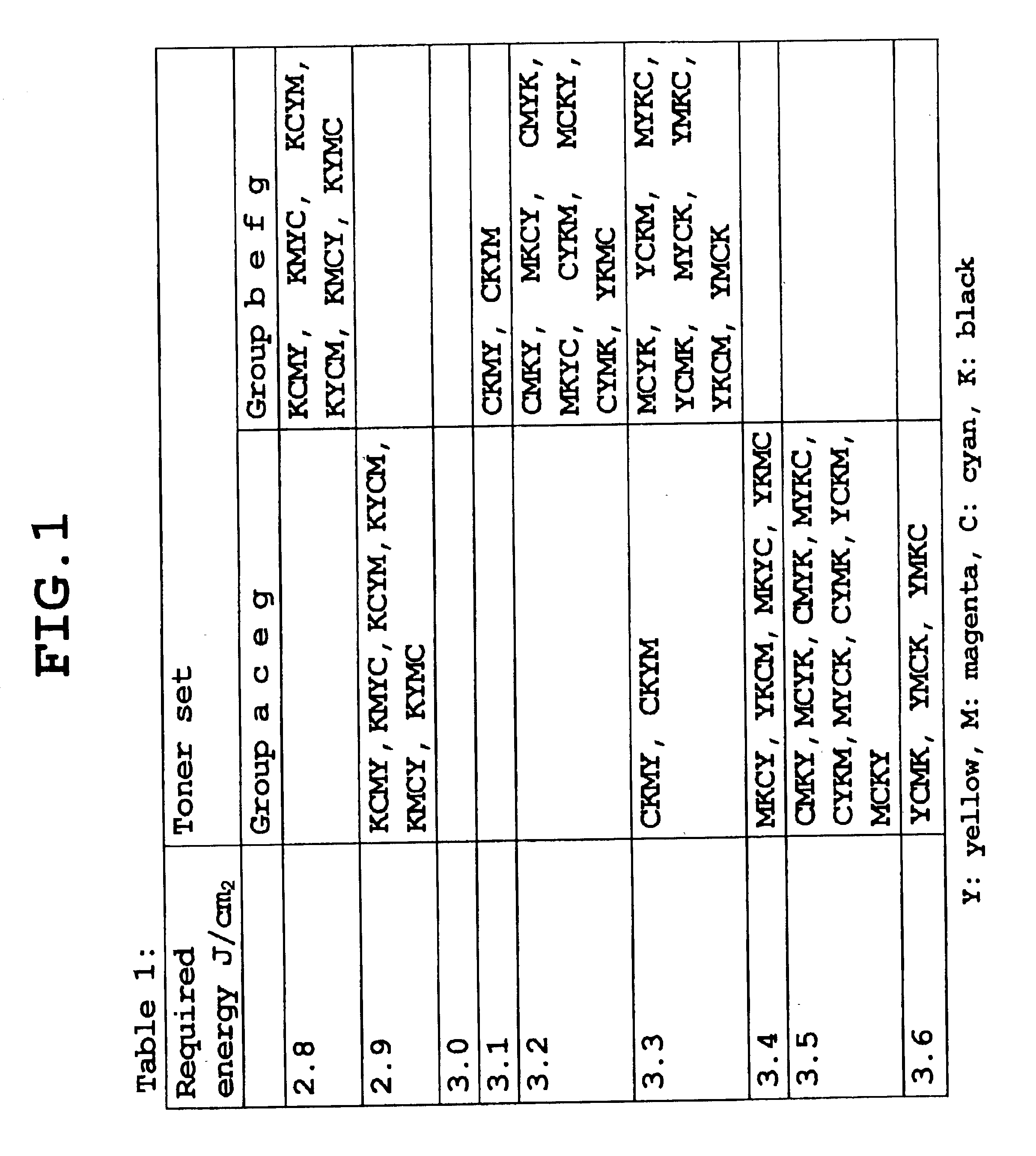
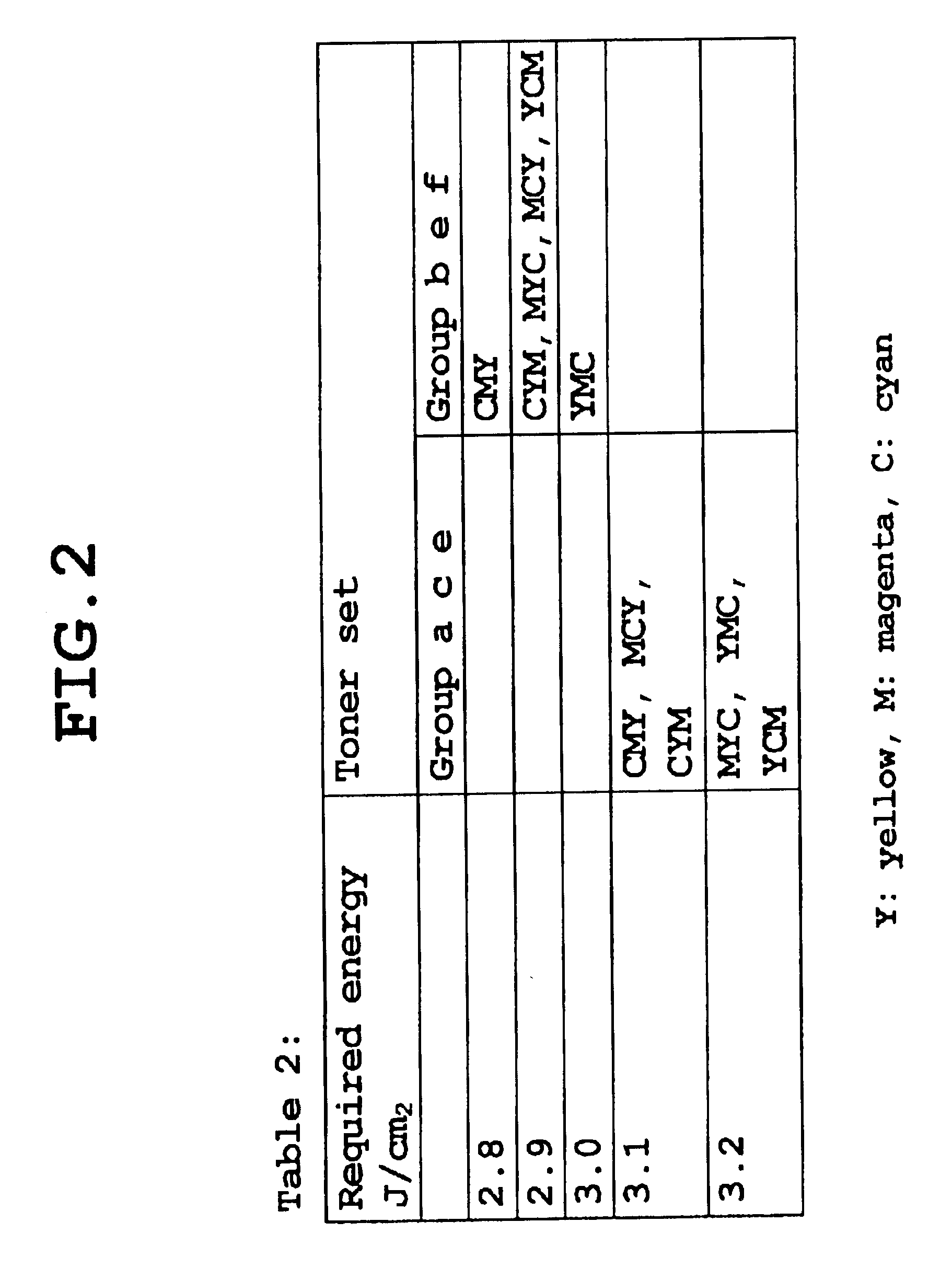
In the following, embodiments of the image formation method of the present invention are described in detail. The image formation method of the present invention uses a plurality of color toners that contain at least a binder resin, a colorant, and an infrared light absorbent. Each of the color toners is laminated one-by-one on a recording medium, such as paper, and a toner powder image is generated. Each layer of the color toners is called a first layer, a second layer, and so on until the n-th layer, the first layer being immediately above the recording medium, and the last layer, i.e., the n-th layer, being the closest to a luminous source. Flashlight irradiation is applied to the laminated toner powder image such that the toner powder image is fused and fixed. This is called “sequential developments and one-time fixing” in the present specification.

Here, the present invention is unique in that the sequence in laying the toners is specified based on a PAS strength value. The PAS ...


PUM


Abstract

The “sequential developments and one-time fixing” method of the present invention specifies that a toner having the greatest PAS strength value should be placed on the top of a lamination of toner layers, which provides efficient radiant energy absorption by the whole lamination of the toner layers, allows efficient heat transmission from the top layer to lower layers, and provides satisfactory color image fixing at relatively low flashing light irradiation energy.

Description

BACKGROUND OF THE INVENTION1. Field of the InventionThe present invention generally relates to an image formation method that uses electrophotography, iono-graphy, and magneto-graphy, and the like, and especially relates to the image formation method wherein a plurality of toners are laminated by developments, and then, all the laminated toners are fixed in one operation that employs radiant energy of a flashlight.2. Description of the Related ArtElectrophotography is widely used in image formation apparatuses, such as copying machines, facsimile machines, and printers. Electrophotography often employs a method that uses an optically conductive insulator, as indicted by U.S. Pat. No. 2,297,691, etc. In this method, an electrostatic latent image is formed by irradiating light from a luminous source, such as a laser and a LED, to the optically conductive insulator that is electrified by a corona electric discharge, or by an electrically charging roller. Then, resin powder colored by p...

Claims


Application Information

Patent Timeline
IPC IPC(8): G03G9/097G03G9/08G03G9/09G03G15/01G03G15/20
CPCG03G9/09708
Inventor KATAGIRI, YOSHIMICHINAKAMURA, YASUSHIGE
Owner FUJIFILM BUSINESS INNOVATION CORP
Why Eureka
Try Eureka