
Control valve assembly of valve assembly-injection-molded control valves or modules

Inactive Publication Date: 2005-01-04
MANN HUMMEL GMBH
View PDF34 Cites 16 Cited by
  • Summary
  • Abstract
  • Description
  • Claims
  • Application Information

AI Technical Summary

Benefits of technology

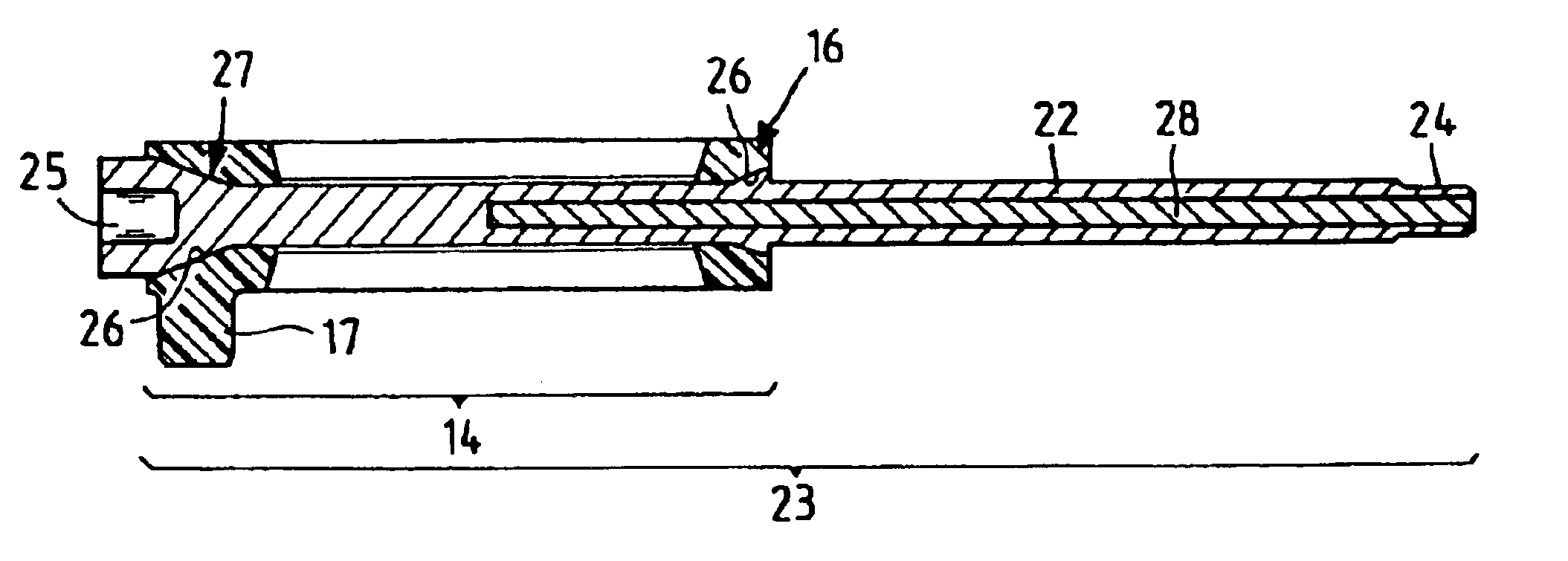
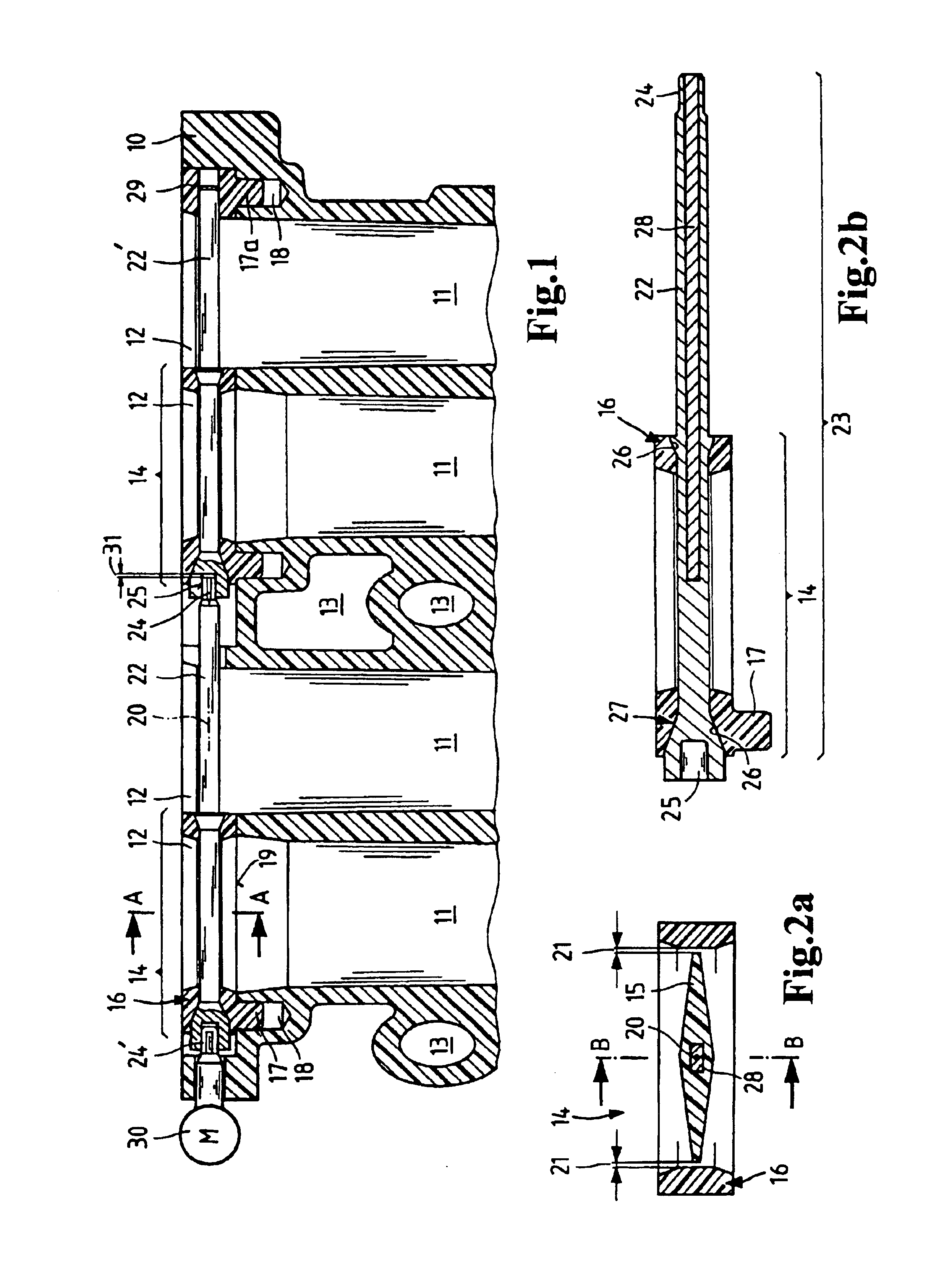
Normally, when the temperature or the air humidity decreases, the valve will shrink more than the valve frame. In such a case it is better to provide a conical bearing configuration which diverges toward the exterior of the frame. Shrinkage of the valve shaft has an axial and a radial component. The radial shrinkage component enlarges or produces a gap between the conical seat in the valve frame and the conical surface on the valve shaft. At the same time, however, axial shrinkage of the valve shaft causes the axis to be shortened so that the gap thus produced is compensated. It is therefore necessary to fix the valve shaft axially. This can advantageously be accomplished by providing a second conical area at the other end of the valve shaft. However, a shoulder on the shaft can also ensure axial fixation. Of course, the valve blades also provide axial fixation of the valve shaft. They limit the axial play of the valve shaft in the opening of the valve frame.
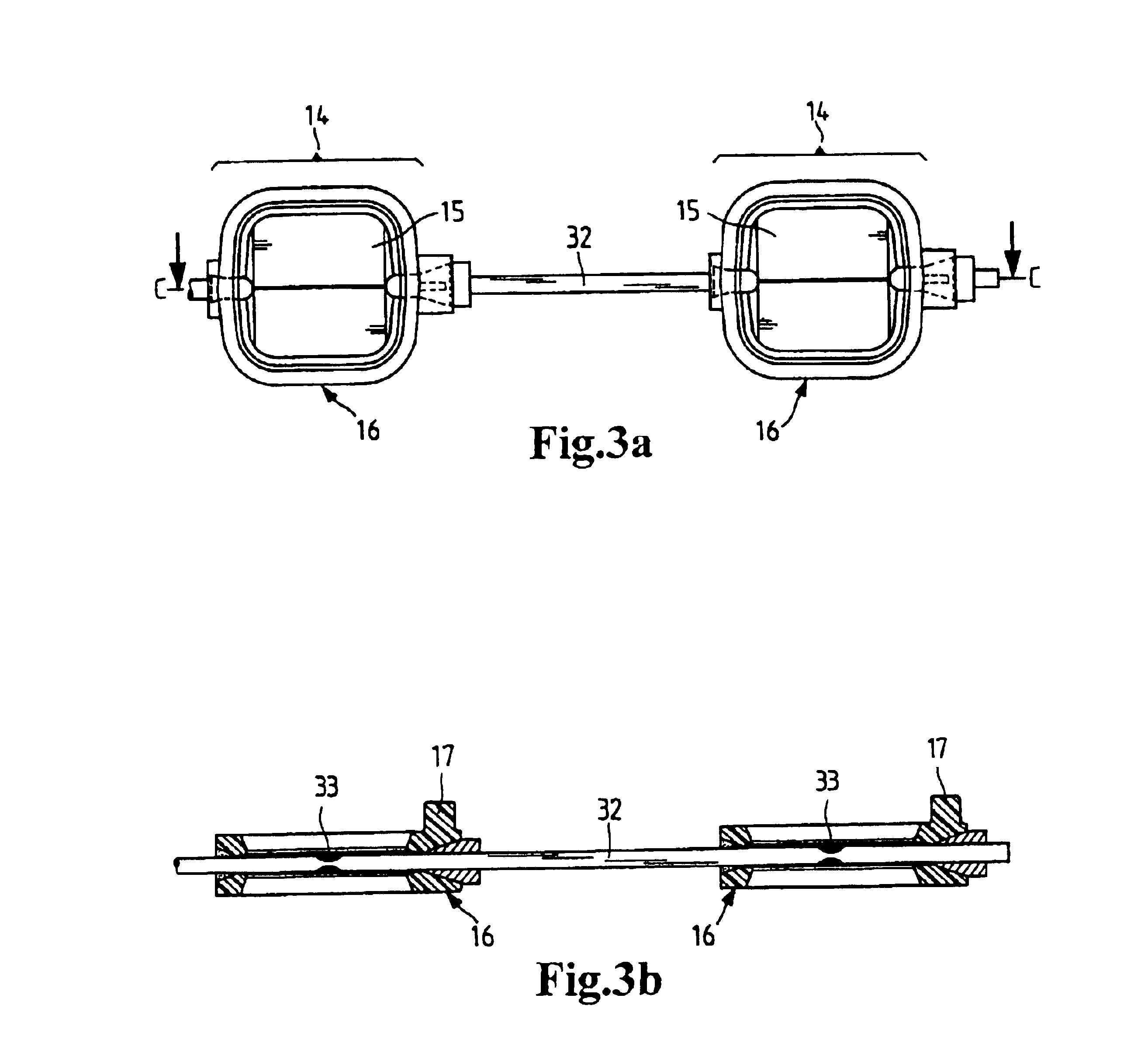
In this embodiment, the valve frames of the individual valve blades need not be separate parts. It is equally feasible to injection mold a large valve frame for all valve blades being used. Particularly advantageous, however, is an embodiment with a plurality of control valves, each of which comprises a valve blade and a valve frame. This provides advantages regarding the axial tolerances between the components. The continuous actuating shaft can be made, for instance, of steel so that shrinkage of the valve blades in axial direction can be largely avoided. Under this condition, the metal actuating shaft can advantageously be completely surrounded by and embedded in the injection molded-valve material to shield it against corrosion.

Problems solved by technology

Such a control valve assembly has drawbacks, however.
Providing cranks increases the material required for the component and ultimately also the component costs.
There are applications, however, where installation space is severely limited.
Particularly if the control valves are to be arranged in the intake channels of an air suction pipe just ahead of the cylinder inlets, the available space is very limited due to the large number of functional components, such as the intake valves.
This causes higher production costs, however, compared to a control valve assembly that is injection molded at the time of assembly.
In addition, assembly is more complex, since the suction pipe housing must be divided in the plane of rotation of the valves to facilitate installation of the valve assembly.

Method used


Image

  • Control valve assembly of valve assembly-injection-molded control valves or modules
  • Control valve assembly of valve assembly-injection-molded control valves or modules
  • Control valve assembly of valve assembly-injection-molded control valves or modules

Examples


Embodiment Construction

Production of the valve assembly with a one-piece actuating shaft requires a modification of the prior art injection molding process at the time of assembly. The forming tool used must make it possible simultaneously to produce at least all the control valves that are used in a control valve assembly. This is achieved by combining the molding for each control valve into one mold cavity. The mold cavities are rotatably supported on the forming tool. The seats for the shaft are formed by core inserts that are laterally inserted into the mold cavities and must be removed prior to casting in the shaft. This requires a certain operating clearance in axial direction relative to the shaft for the core inserts. Since this clearance is not generally available due to the required spacing between the control valves, the mold cavities can be twisted for optimal accessibility for handling tools. It is advisable to produce the valve frames in a position of the mold cavities in which the orientati...


PUM

PropertyMeasurementUnit
Interferenceaaaaaaaaaa
Areaaaaaaaaaaa
Stiffnessaaaaaaaaaa

Abstract

A control valve assembly comprising at least two control valves which may be used, for example, to throttle the air intake of an internal combustion engine. The assembly is provided with a centrally arranged, force-transmitting shaft (32). The control valves are formed by blades (15) in frames (16) produced by an assembly injection molding process. The control valve blades (15) can be molded onto the force-transmitting shaft (32). The resulting assembly can be mounted or installed as a unit. Alternatively, instead of using a single continuous shaft, shaft projections can be injection molded on the valve blades, which terminate in lugs which engage in a rotationally secure manner in sockets in an adjacent valve assembly so that the two assemblies rotate together as a unit. The resulting control valve assembly is easy to install and advantageously takes up only a little space.

Description

BACKGROUNG OF THE INVENTIONThe invention relates to a control valve assembly comprising at least two control valves produced by assembly injection molding, a process in which a molded part is produced assembled to another part by injection molding it in place in the other part. The invention further relates to a control valve module comprising a plurality of such control valve assemblies.The use of control valves that are injection molded at the time of assembly is known, for example, in the automotive field. Karlsson et al., U.S. Pat. No. 5,304,336 (=EP 482 272) in FIG. 5 illustrates the production process for assembly-injection-molded control valves. These control valves are produced in a mold. Core inserts 3, 4, 7, 8 can be moved within the mold in such a way that the valve blades and the shaft can be produced in one piece in the previously injection molded valve frame. Since the plastics of the valve blades and the valve frame do not adhere to one another, the vanes and frame ca...

Claims


Application Information

Patent Timeline
IPC IPC(8): F02D9/10F02B27/02F02D9/08F16K1/22B29C45/14
CPCB29C45/14311F16K1/223F02B27/0273F02D9/1095B29C45/14549B29K2705/00B29L2031/7506Y10T29/49426Y02T10/146Y10T29/49417Y10T137/87161Y10T137/0525Y10T137/6048Y02T10/12F01L15/14
Inventor RENTSCHLER, KLAUSNEUSCHWANDER, HELMUT
Owner MANN HUMMEL GMBH
Learn More