
Optical disk device and information reproducing device performing maximum decoded offset process, and reproducing methods thereof

a technology of optical disk and offset process, applied in the field of optical disk device, can solve the problems of insufficient decoding of viterbi decoder, inability to perform pll circuit satisfactorily, and complex circuits

Inactive Publication Date: 2004-06-22
KK TOSHIBA
View PDF5 Cites 12 Cited by
  • Summary
  • Abstract
  • Description
  • Claims
  • Application Information

AI Technical Summary

Benefits of technology

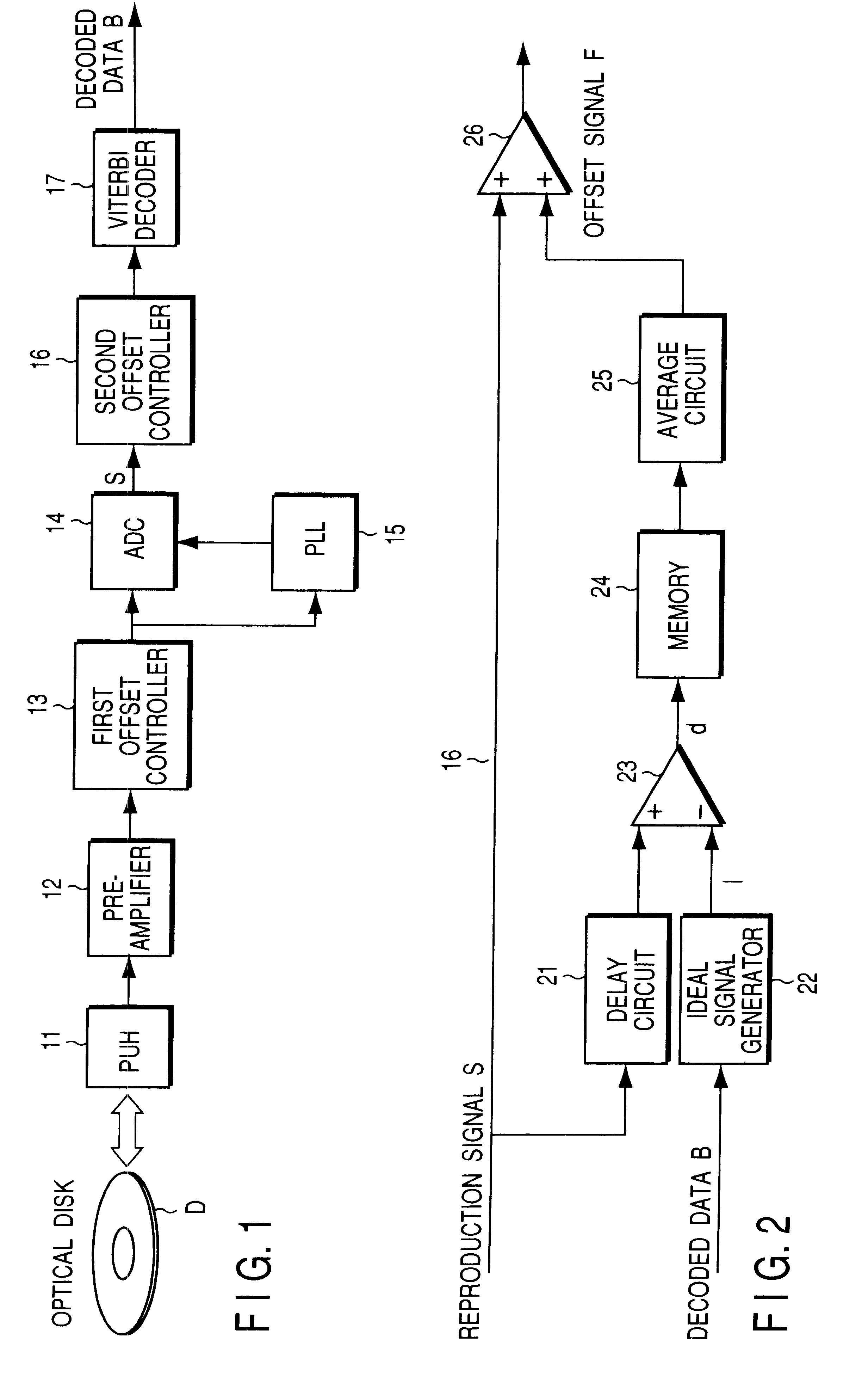
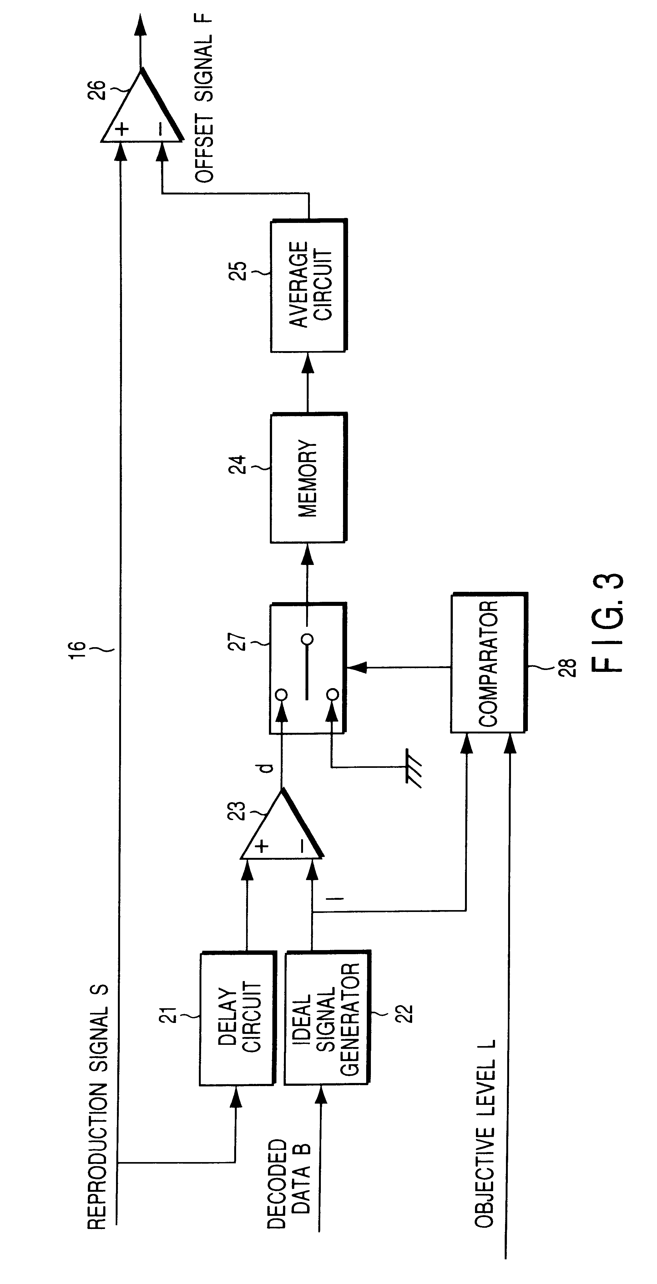
That is, according to the invention, without an offset for the A / D converter, but if an offset value is separately obtained for viterbi decoder and the reproduction signal is offset according to the obtained value, it is possible to provide an optical disk device capable of eliminating the asymmetry (asymmetric element) unfailingly with the offset value for the viterbi decoder and decoding the reproduction information with high identification accuracy. As a result, it is possible to reproduce highly accurate recording information from which the asymmetry (asymmetric element) has been eliminated through a simple circuit structure.

Problems solved by technology

In such an optical disk device, in a case where a great deal of asymmetry that is asymmetric element is included in the reproducing signal, if an offset value is determined so as to achieve sufficient performance of the PLL circuit and added, the viterbi decoder cannot be performed sufficiently.
On the contrary, when the offset value is set so as to achieve the performance of the viterbi decoder and added, the PLL circuit cannot be performed satisfactorily.
Further, a problem lies in that, when it is attempted that the asymmetry (asymmetric element) is eliminated by obtaining the average level, in all of the reference levels, for example, about the level-7 in PR (1, 2, 2, 1) characteristics to use a reference level of the viterbi decoder, the circuits become very complicated.

Method used


Image

  • Optical disk device and information reproducing device performing maximum decoded offset process, and reproducing methods thereof
  • Optical disk device and information reproducing device performing maximum decoded offset process, and reproducing methods thereof
  • Optical disk device and information reproducing device performing maximum decoded offset process, and reproducing methods thereof

Examples


Embodiment Construction

>

Further, as an embodiment of the invention, FIGS. 6 and 7 are block diagrams showing an example of another optical disk device of the PRML method. FIG. 13 is a block diagram showing another example of the optical disk device of the PRML method according to the invention.

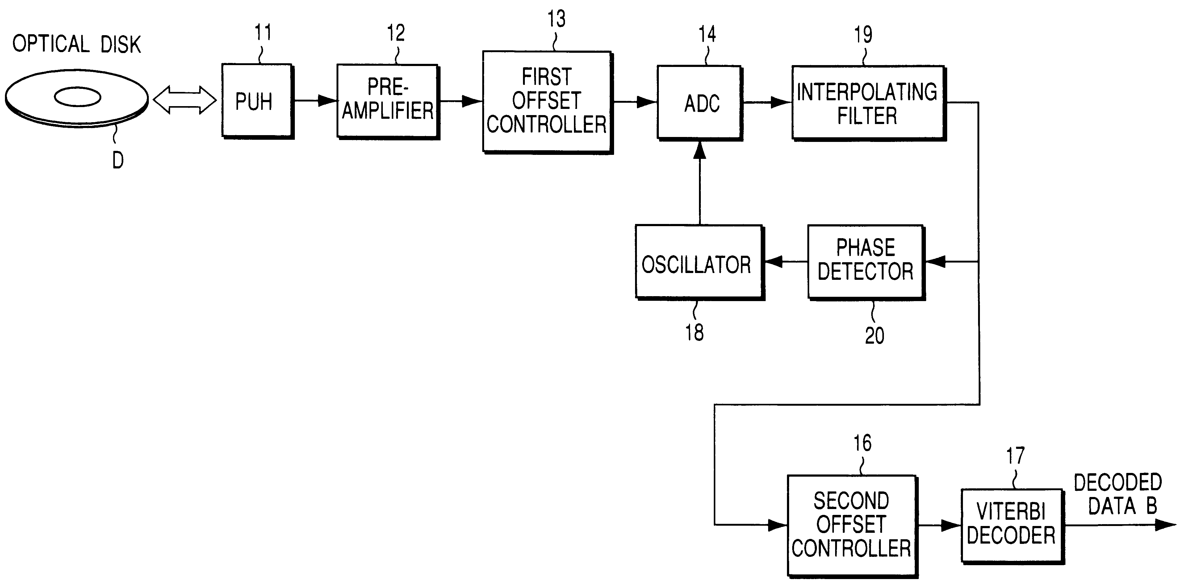
That is, in the aforementioned embodiment, the example has been described in that an analog PLL circuit is used. However, in the present invention it is possible to adopt a method of using a digital PLL circuit shown in FIG. 6. In this case, a clock signal is generated in the PLL circuit 15 based on the converted digital signal.

Further, the invention can be applied to a method of using asynchronous sampling method shown in FIG. 7. The A / D converter 14 is operated by the clock from an oscillator 18, and an interpolating filter 19 involving a phase detector 20 is also provided.

And further, in the embodiment described above, the example of the PR (1, 2, 2, 1) characteristic and the (1, 7) RLL code is described. However...


PUM


Abstract

An optical disk device has reproduction signal detecting section, each of which detects a reproduction signal corresponding to a reflective wave of an optical disk, a first offset controller, which offsets the reproduction signal with a first offset value F1, an A / D converting circuit, which A / D converts the offset reproduction signal, and a second offset controller, which offsets the converted digital reproduction signal with a second offset value F2, and a decoder, which viterbi decodes the offset digital reproduction signal and outputs decoded data B. Because an offset is performed with each exclusive value to A / D conversion and viterbi decoding, it is possible to obtain high identification accuracy with nonlinear characteristic eliminated.

Description

This application is based upon and claims the benefit of priority from the prior Japanese Patent Application No. 2001-395288, filed Dec. 26, 2001, the entire contents of which are incorporated herein by reference.1. Field of the InventionThis invention relates to an optical disk device using a PRML method, in particular, to a PRML method optical disk device that performs a maximum decoded offset process.2. Description of the Related ArtRecently, there has been widely spread an optical disk device that performs a recording and reproducing process to an optical disk such as a DVD (Digital Versatile Disk), which has been developed variously and produced. For example, as a method of recording and reproducing process of an optical disk device, there is a PRML (Partial Response and Maximum Likelihood) method.In a conventional optical disk device that does not have characteristics of the present invention, in general, information recorded in an optical disk is reproduced as faint analog si...

Claims


Application Information

Patent Timeline
IPC IPC(8): G11B20/14G11B20/10G11B7/00G11B7/005
CPCG11B20/10009G11B20/10055G11B20/10111G11B20/10296G11B20/10425
Inventor KASHIHARA, YUTAKATAKEHARA, SHINTARO
Owner KK TOSHIBA
Learn More