Eureka AIR delivers breakthrough ideas for toughest innovation challenges, trusted by R&D personnel around the world.

Method and system for detecting events

a technology of event detection and event information, applied in the direction of simultaneous measurement of multiple fluid pressure valves, speed/acceleration/shock measurement, pressure difference measurement between multiple valves, etc., can solve the problem of reducing the value of information, unreliability and inaccuracy of information, and difficulty in making correct interpretations that adequately contain necessary information, etc. problem, to achieve the effect of achieving the correct content of event information, ensuring accuracy, and ensuring accuracy of event information

Active Publication Date: 2011-01-06
MARMILS OY
View PDF20 Cites 14 Cited by
  • Summary
  • Abstract
  • Description
  • Claims
  • Application Information

AI Technical Summary

Benefits of technology

[0038]An advantage of the invention with respect to prior-art solutions is e.g. that with the method and the system it is possible to produce appropriate information about the events of the space to be monitored in a format that is well suited to the use of people and equipment. The method and the system identify events according to given event conditions with great accuracy such that event information with the correct content that describes an event is formed about exactly the desired events of the target space. The method and system according to the invention allow the detection and identification of events according to the defined use of each room such that event information is obtained about exactly those events about for information is needed. Furthermore, accuracy of the identification of events as well as correctness of the content of event information is achieved that are better than what can be achieved with economically comparable prior-art solutions. An advantage of the invention with respect to prior-art solutions is the high utility value of the observation information produced by processing the sensor observations and / or of the event information produced on the basis of it compared to the equipment resources required for producing and analyzing the information, e.g. to the amount of processing capacity or of memory.

Problems solved by technology

The problems of prior art solutions are the difficulty of making the correct interpretations that adequately contain the necessary information using sensor observations that are instantaneous or of very short duration.
The unreliability and inaccuracy of information reduces its value.
The problem of camera surveillance is that it typically requires that a person interprets the surveillance images in order for events that require actions, or that otherwise need detecting, to be detected.
The automated interpretation of images requires expensive equipment, and often the interpretation of images anyway requires that a person makes an interpretation in order to achieve adequate accuracy of the content of the event information and reliability of the information.
The problem with these solutions is that only those objects to which an identifier has been fixed are detected.
An active identifier provided with a power source is used in some solutions, a problem in which is the duration of the power source, because typically there are very many excitation transmitters that activate the identifier in the space to be monitored and the identifier correspondingly activates many times.
One problem of prior-art solutions that produce event information is the great need for processing power required to identify an object and the events linked to the object.
On the other hand, one problem is also the relatively high amount of errors that occur in identification.
More particularly, reliable identification of events linked to the tracked object by utilizing prior-art solutions has proven to consume resources and to be prone to operational error.
In prior-art solutions, the inflexibility of the solution is a problem when using detectors installed in locations, or targeted at them, as the object of the monitoring.
Changes require actions that during the lifecycle of the solution incur substantial modification costs and equipment costs, and also restrict the use of the spaces during the modification process.

Method used


Image

  • Method and system for detecting events
  • Method and system for detecting events
  • Method and system for detecting events

Examples


Embodiment Construction

[0045]In the following the invention will be described in more detail with reference to the embodiments presented as examples and to the attached drawings, wherein

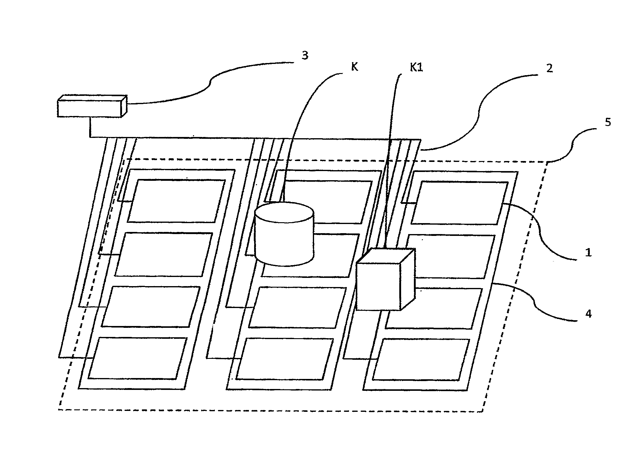
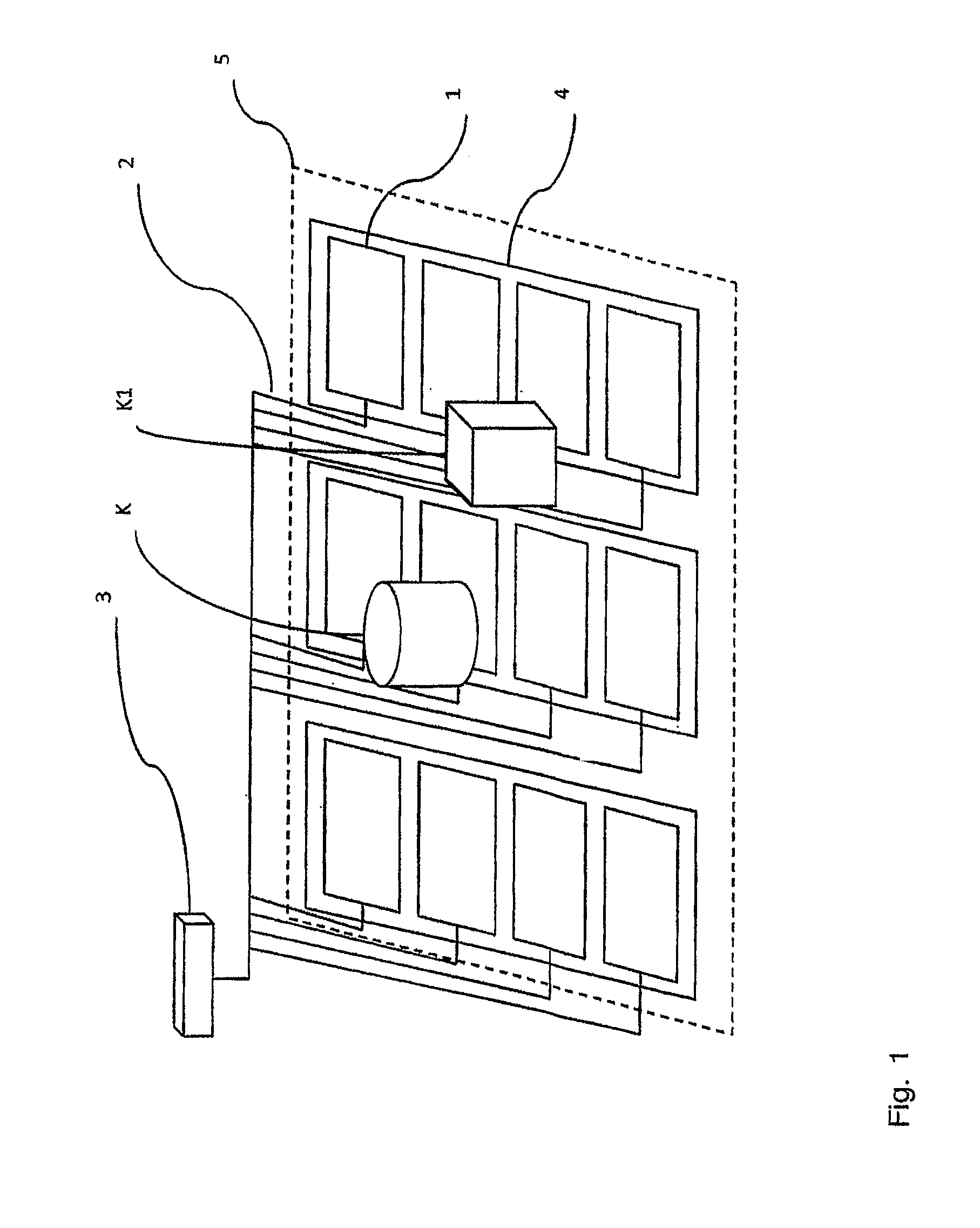
[0046]FIG. 1 presents one system according to the invention.

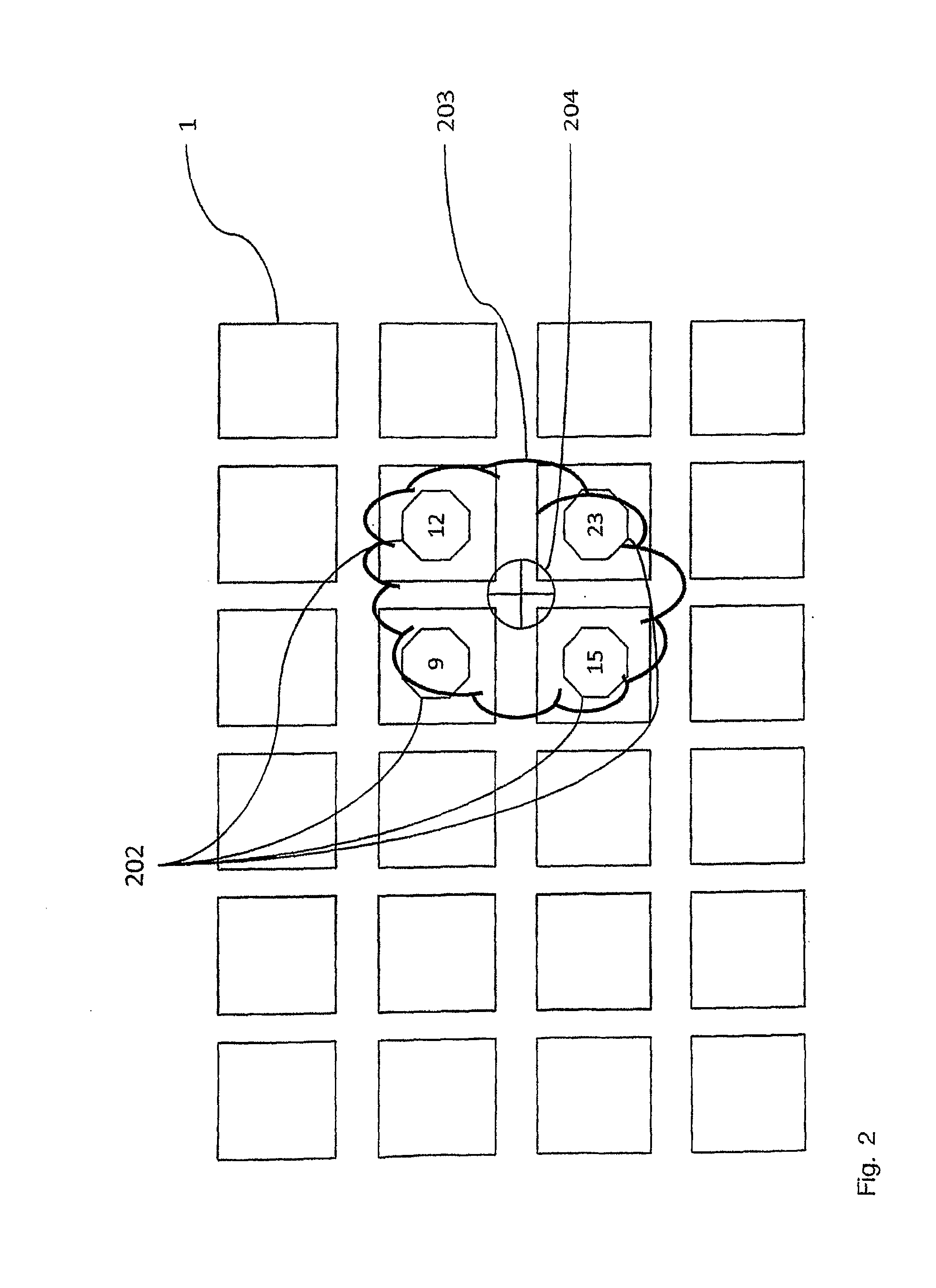
[0047]FIG. 2 presents by way of example the linking of sensor observations to the object according to the invention.

[0048]FIG. 3 presents an example of the sensor observations produced by a person falling and of the tracking of an object in a system according to one embodiment of the invention.

[0049]FIG. 4 presents the observations produced by two objects approaching and meeting each other, and the processing of these in the system according to one embodiment of the invention.

[0050]FIG. 5 presents the sensor observations produced by a person getting out of bed in the system according to one embodiment of the invention.

[0051]FIG. 6 presents the sensor observations produced an object moving to beside the bed at sequential moments of time and the processing of the ob...


PUM


Abstract

The system according to the invention interprets sensor observations by tracking objects and by collecting information about the objects by means of the tracking and by using this information for affirming events linked to the objects and in producing information describing the events. The system detects events according the conditions defined for them, on the basis of sensor observations. The conditions can relate to the essence of the objects, e.g. to the strength of the observations linked to the object, to the size and / or shape of the object, to a temporal change of essence and to movement. The event conditions used by the system can comprise conditions applying to the location of the object. The system according to the invention can be used e.g. for detecting the falling, the getting out of bed, the arrival in a space or the exit from it of a person by tracking an object with a dense sensor field, and for producing event information about the treatment or safety of the person for delivering to the person providing care.

Description

FIELD OF THE INVENTION[0001]The object of this invention is a method and a system for tracking objects that uses a dense sensor field.PRIOR ART[0002]In prior-art solutions the presence, location and movement of people, animals, objects and devices are detected using microwave radars or ultrasound radars, infrared detectors, video imaging and analysis of it, near-field sensors installed in the floor, pressure sensors or separate touch sensors used on top of the floor covering.[0003]In prior-art solutions detection of an object is based on making an observation that covers a short period of time, or that is instantaneous, with detectors or sensors. The area to be monitored is covered with detectors or sensors, or a sensor or detector is disposed in a local object, and each observation produced by the sensor or detector that is stronger than a threshold value and exceeds a set limit for its duration is used to affirm an event of the object of interest. In some cases the condition for a...

Claims


Application Information

Patent Timeline
Patent Type & Authority Applications(United States)
IPC IPC(8): G06F15/00
CPCG08B13/10G08B21/0469G08B21/0461G08B21/043G08B21/22
Inventor LINDSTROM, JUHAAUTERINEN, OTSO
Owner MARMILS OY
Why Eureka
Eureka Blog
Learn More