
Analytical method and apparatus

an optical surface and analytical method technology, applied in the direction of measuring devices, scattering properties, instruments, etc., can solve the problems of limited technique, one-dimensional sensor area, spr-based methods used,

Inactive Publication Date: 2004-03-30
GE HEALTHCARE BIO SCI CORP
View PDF4 Cites 85 Cited by
  • Summary
  • Abstract
  • Description
  • Claims
  • Application Information

AI Technical Summary

Benefits of technology

"The present invention relates to a method and apparatus for optical surface analysis using surface plasmon resonance (SPR) techniques. The technical effects of this invention include improved accuracy and sensitivity in measuring molecular interactions and the ability to measure changes in refractive index at a specific location on a sensor surface. The invention also eliminates the need for bulky mechanical axes and introduces a faster and more efficient method for detecting SPR."

Problems solved by technology

A disadvantage of that approach is, however, that when scanning the incident angle by means of a plane mirror, the point where the light beam hits the sensor surface will move along the internal reflection surface of the prism.
This technique is limited in that it enables only a one-dimensional sensor area, which is restricted to the cross-section of the light line with the sensor area.
Therefore, such SPR-based methods used to measure, for example, inter alia protein interactions are limited to quantitative information for sensing areas localized in one spot or one row of spots on the surface where a specific interaction takes place.
This method requires, however, the use of scanning mirrors for both addressing the sensor zones and scanning the angle and complex and expensive processing of angular and positional data from the mirror-scanners and photodetectors, which limits the detection rate.
Drawbacks with mechanically scanned SPR-sampling includes that a high lateral resolution and high speed for "real time monitoring" demands a complex and expensive scanning mechanics (due to the bulkiness of the illumination and detection device).
It is readily understood that such variation of the incident angle based on rotation of the mechanical axis carrying illuminating, imaging and detector modules is rather slow and inaccurate if not a complex and expensive design is provided.
A disadvantage is, however, that the probed spot is not stationary during the angular scan, i.e., all sites within a sensing area are not probed by light at an equal angle of incidence range, unless bulky optics is covering the sensing area at an excess.
Since this apparatus uses one dimension in the image plane for a real image, and the other dimension for projecting the reflectance versus angle of incidence, it could not, however, provide a two-dimensional image of the refractive index distribution.
The prior art microscopy systems described above do not permit a sufficiently rapid, sensitive and accurate scanning and measurement of the incident angle to permit highly quantitative multi-site real-time monitoring of a sensor surface.
Further, they are only suitable for imaging a limited sensor area of up to about 1.times.1 mm.sup.2.
They are also too laborative and operator-dependent to be used in a commercial analytical instrument.
The necessary high refractometric sensitivity for determining the refractive index of the sensor surface with an apparatus constructed according to the above prior art in a long-term accurate commercial analytical instrument could therefore only be achieved with a very complex and expensive design.
A varying light intensity during the scan mode of the invention, e.g., as caused by SPR also within this part of the detected light, is likely to disturb the accuracy of the angular determination.

Method used


Image

  • Analytical method and apparatus
  • Analytical method and apparatus
  • Analytical method and apparatus

Examples


Embodiment Construction

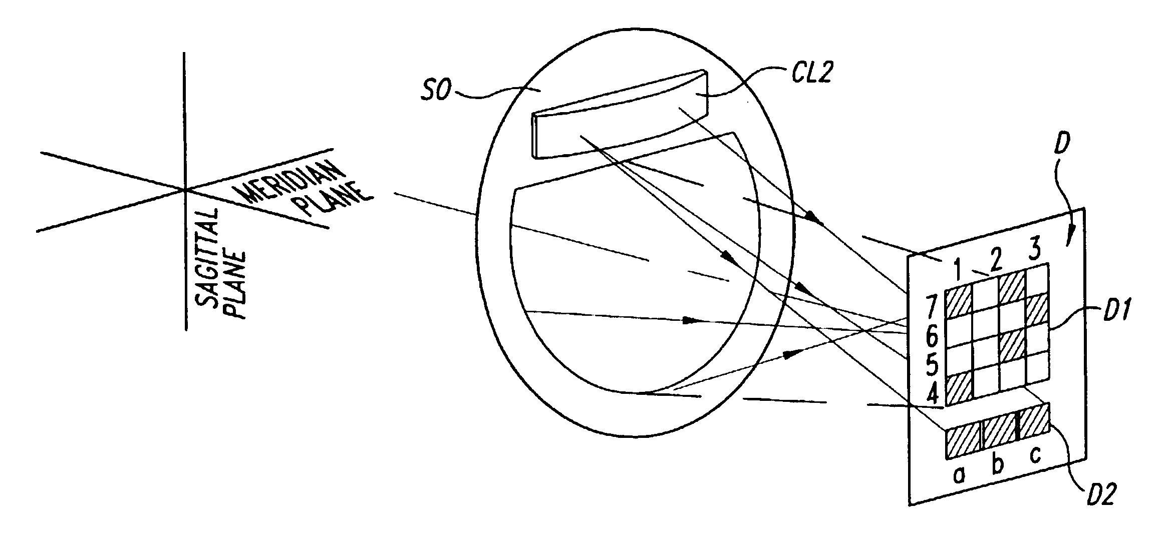
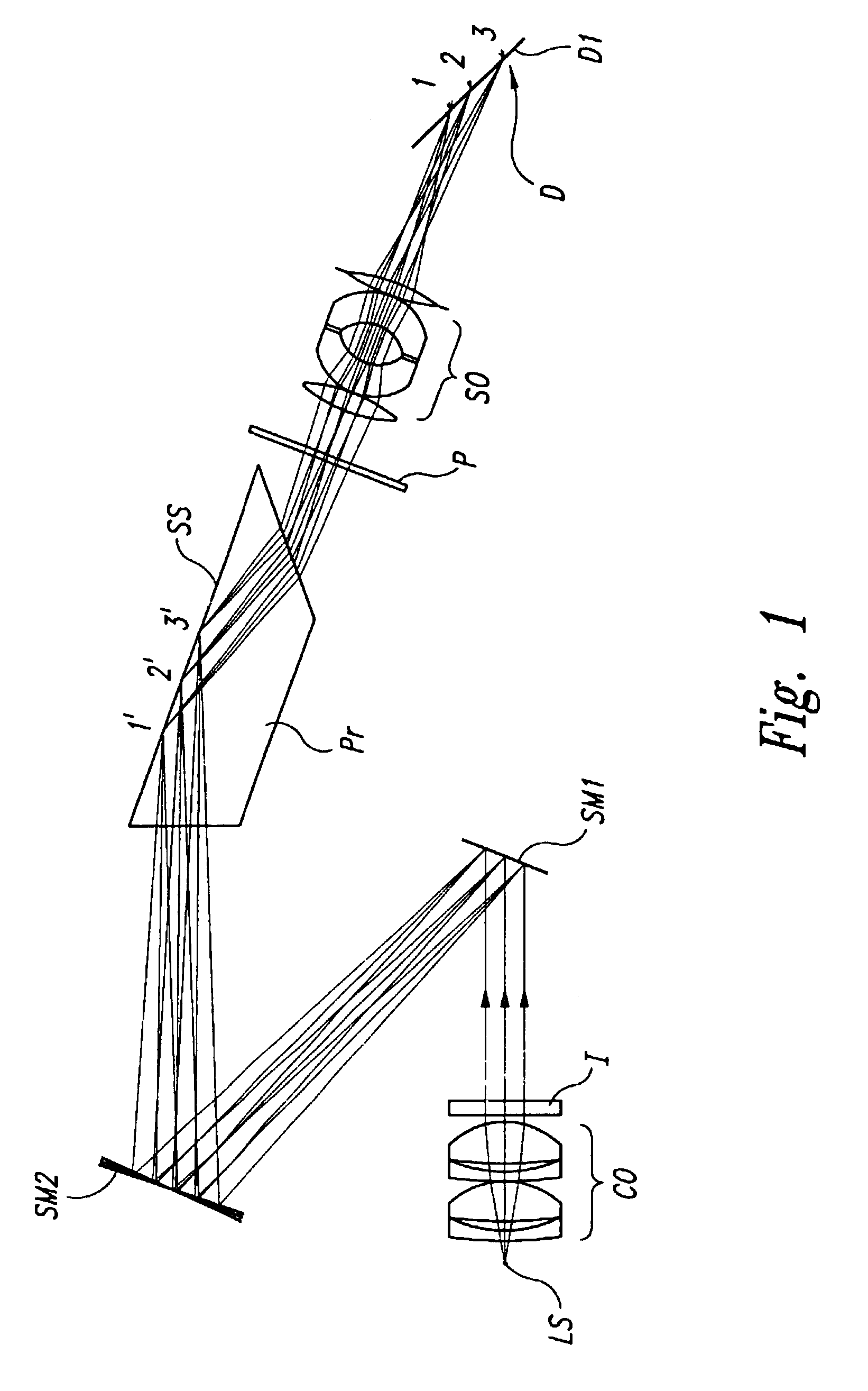
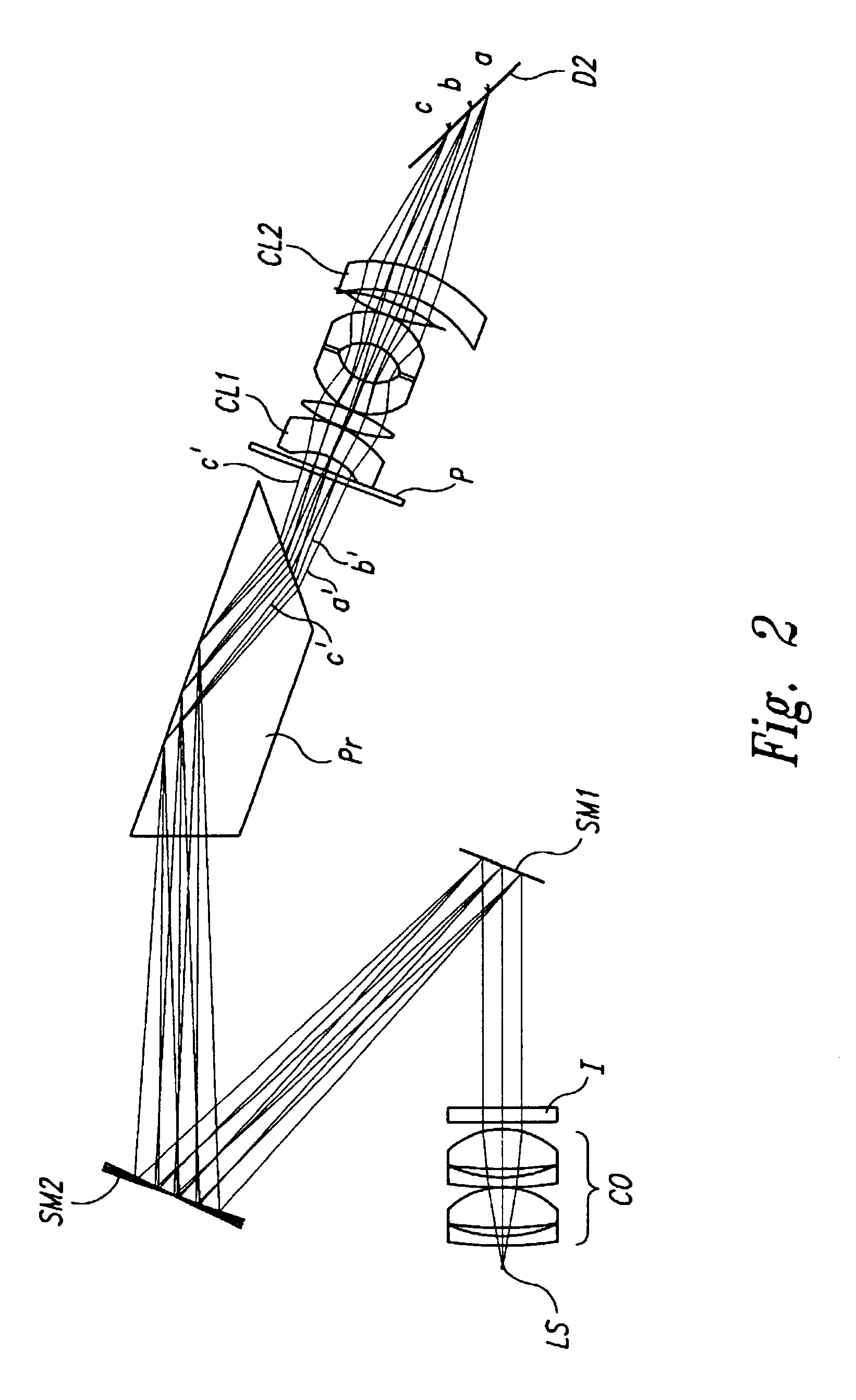
The principle of the present invention was verified as demonstrated in FIGS. 24a-24d, by use of a pivotally moving illumination system similar to the one described in FIG. 22, using a light emitting diode of center-wavelength 766 nm, lenses and a sheet-polarizer providing p-polarized collimated beam of diameter 8 mm, an interference filter of bandwidth 3 nm, an imaging embodiment according to FIGS. 3, 4, and 5, and a CCD-photodetector matrix connected to a video-recorder. The obscuration, imaged as the dark right part in FIGS. 24a-24d covering about 25% of the image, is positioned at the interference filter I, FIG. 23, decentered in relation to the beam cross-section, so that it covers about 15% of the beam width.

FIGS. 24a-24d show a series of SPR-images of a sensor surface exposed to rinse solution in a flow cell, the sensor surface consisting of sixteen zones of various refractive index (optical thickness), zone size 0.5 mm.times.0.5 mm, each image at a specific angle of incidence...


PUM

PropertyMeasurementUnit
diameteraaaaaaaaaa
diameteraaaaaaaaaa
lengthaaaaaaaaaa

Abstract

A method of examining thin layer structures on a surface for differences in respect of optical thickness, which method comprises the steps of: irradiating the surface with light so that the light is internally or externally reflected at the surface; imaging the reflected light on a first two-dimensional detector; sequentially or continuously scanning the incident angle and / or wavelength of the light over an angular and / or wavelength range; measuring the intensities of light reflected from different parts of the surface and impinging on different parts of the detector, at at least a number of incident angles and / or wavelengths, the intensity of light reflected from each part of the surface for each angle and / or wavelength depending on the optical thickness of the thin layer structure thereon; and determining from the detected light intensities at the different light incident angles and / or wavelengths an optical thickness image of the thin layer structures on the surface. According to the invention, part of the light reflected at said surface is detected on a second detector to determine the incident angle or wavelength of the polarized light irradiating the surface. An apparatus for carrying out the method is also disclosed.

Description

1. Field of the InventionThe present invention relates to a method and an apparatus for optical surface analysis of a sample area on a sensor surface.2. Description of the Related ArtThe interest for surface sensitive measuring techniques has increased markedly recently as several optical techniques have been developed for identifying and quantifying molecular interactions, which techniques do not require labelling. The most used optical technique so far is based on surface plasmon resonance, hereinafter frequently referred to as SPR.The phenomenon of surface plasmon resonance, or SPR, is well known. In brief, SPR is observed as a dip in intensity of light for a specific wavelength reflected at a specific angle (as measured by, e.g., a photodetector) from the interface between an optically transparent material, e.g., glass, and a thin metal film, usually silver or gold, and depends on among other factors the refractive index of the medium (e.g., a sample solution) close to the metal...

Claims


Application Information

Patent Timeline
Patent Type & Authority Patents(United States)
IPC IPC(8): G01B11/06G01N33/543G01N21/27G01N21/55
CPCG01B11/0625G01N21/552G01N21/553G01N2021/212G01N2021/215
Inventor IVARSSON, BENGT
Owner GE HEALTHCARE BIO SCI CORP
Learn More