System and method for heterodyning an ultrasonic signal

Inactive Publication Date: 2004-03-16
U E SYST
View PDF9 Cites 52 Cited by
  • Summary
  • Abstract
  • Description
  • Claims
  • Application Information

AI Technical Summary

Benefits of technology

The present inventors have determined that a heterodyned signal that drives a meter requires a relatively large dynamic range, but a limited frequency response, while a heterodyned signal that is required for headphones or spectral analysis may have a low dynamic range, but requires high resolution. Further, it has been found that the resolution or frequency response of the input transducer signal is degraded if a single heterodyning circuit is used to drive a number of circuits or meters with competing requirements. In order to overcome these competing requirements, the present invention uses a dual heterodyning circuit in which the two individual heterodyne circuits are separately optimized so that the second results in a signal with a large dynamic range and the first results in a signal with a great resolution, and neither unduly loads the transducer array or obscures subtle frequency components. This permits the capture of particularly low level frequency components for extraction during spectral analysis.
In accordance with the invention, the first heterodyning circuit has a feed back loop filter and a transformer to provide an enhanced spectral (i.e., frequency) response. This circuit is used to drive the headphone, a wave file generator and a line output. This signal, which has a modest dynamic range but a high frequency response and a low signal to noise ratio, allows the spectrum of the signal to be analyzed in real time by an external spectrum analyzer, recorded for later analysis or listened to in real time through the headphones.
The second heterodyning circuit has a smaller frequency response but a larger dynamic range so that it can drive the meter. In accordance with the invention, the second heterodyne circuit is not required to have an optimized spectral response. If the meter were driven with the first heterodyne circuit, the impedance and dynamic range requirements of the meter would adversely affect the response. Thus, two heterodyne circuits are used, with the circuit that drives the meter being simpler, and less costly to manufacture and having a larger dynamic range.
By using the dual heterodyning circuit of the present invention to provide the enhanced spectrum, it becomes clear whether a detected resonance is mechanical or electrical. In addition, fault frequencies are also more easily discernable. In other words, the enhanced signal output provides a lower signal-to-noise ratio, so as to increase the ease with which frequency components are analyzed.

Problems solved by technology

Additionally, faulty devices, such as bearings, generate a higher level of ultrasonic energy than do good bearings and thus, this condition can also be detected.
Since ultrasonic energy used for these purposes is generally in the range of 40 kHz, it is too high in frequency to be heard by a human being.
However, this attenuation method does not provide a way to establish fixed reference points to allow for repeatable measurements.
However, the detector disclosed in Peacock does not process the detected signal to produce an audible response, nor does it provide for signal attenuation after the initial pre-amplification stage.
It has been found, however, that with such an arrangement a typical transistor pre-amplifier loads the transducers to such an extent that the gains achieved by stacking them serially are lost.
Unfortunately, the transducers in this arrangement are not placed so that they both readily receive ultrasonic energy.
Thus, the Morris arrangement is not entirely satisfactory.
Further, it has been found that the resolution or frequency response of the input transducer signal is degraded if a single heterodyning circuit is used to drive a number of circuits or meters with competing requirements.
If the meter were driven with the first heterodyne circuit, the impedance and dynamic range requirements of the meter would adversely affect the response.
In either mechanical analysis or electrical equipment analysis, a large number of frequencies in the low frequency range become lost.
However, it is extremely difficult for a person to discern with their ears the differences between inputs that are electrical in nature and inputs that are vibrational.
Further, in other technologies, such as vibration analysis, infrared technologies, or where rotational equipment is used, the use of the human ear is a highly unreliable way in which to predict faults.
When an operator listens to the cabinet containing the component that is vibrating at the 60 Hz, it is impossible to determine whether the resonance is electrical or mechanical.

Method used


Image

  • System and method for heterodyning an ultrasonic signal
  • System and method for heterodyning an ultrasonic signal
  • System and method for heterodyning an ultrasonic signal

Examples


Embodiment Construction

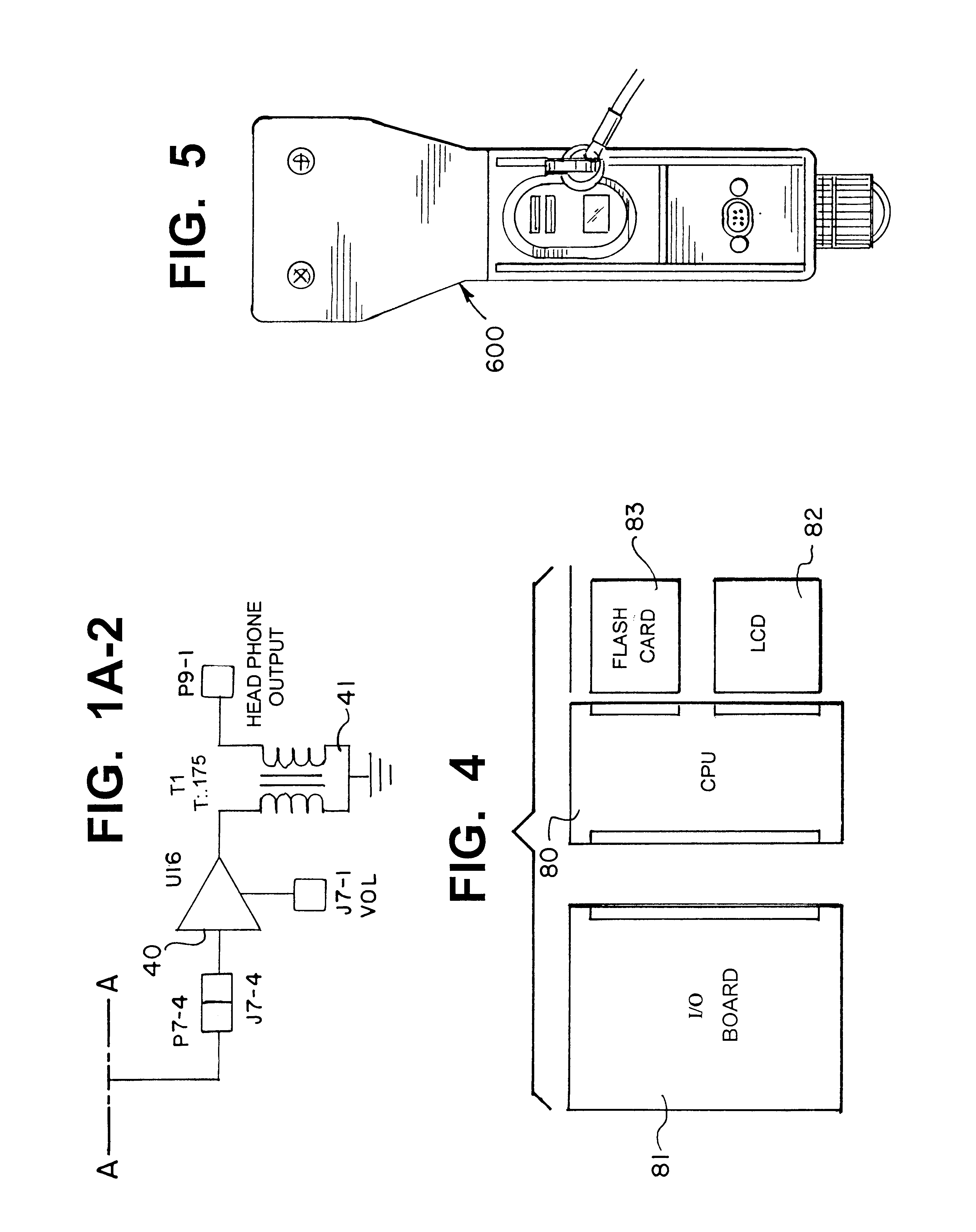
FIG. 6 is a perspective view of a portable ultrasonic detector. Toward the front of the housing there are ultrasonic transducers 95, as shown in FIG. 8. Micro-processor controlled circuits for heterodyning the ultrasonic signal to shift its frequency to the audio range are contained in the body of the housing. A display 82 is located at the back so the operation and the results can be viewed. At the back, there is also a jack 88 for headphones, so that the user can listen to the audio sound during a test, e.g., as a way of locating a leak. Other jacks and controls are located on the body or will be described subsequently.

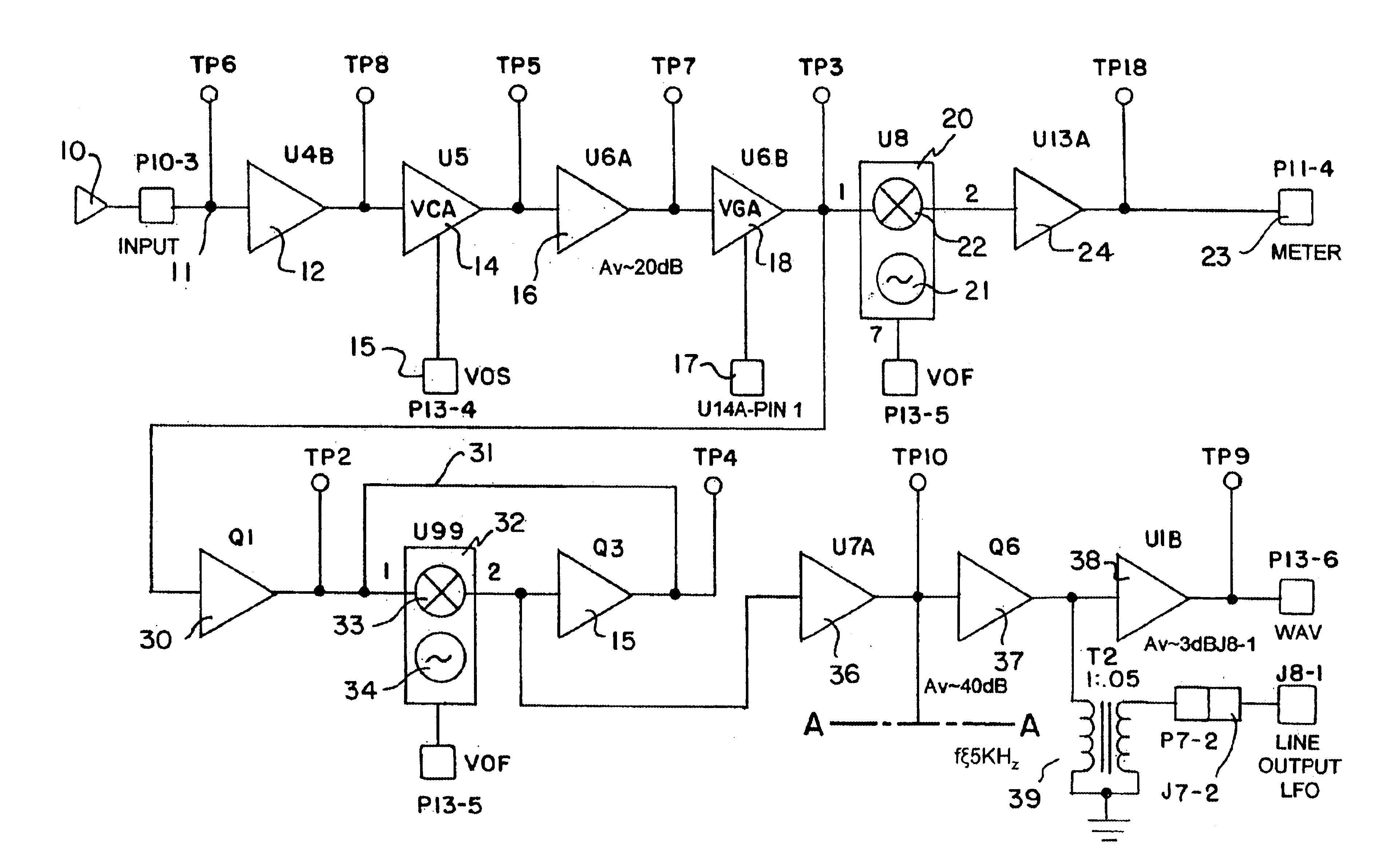
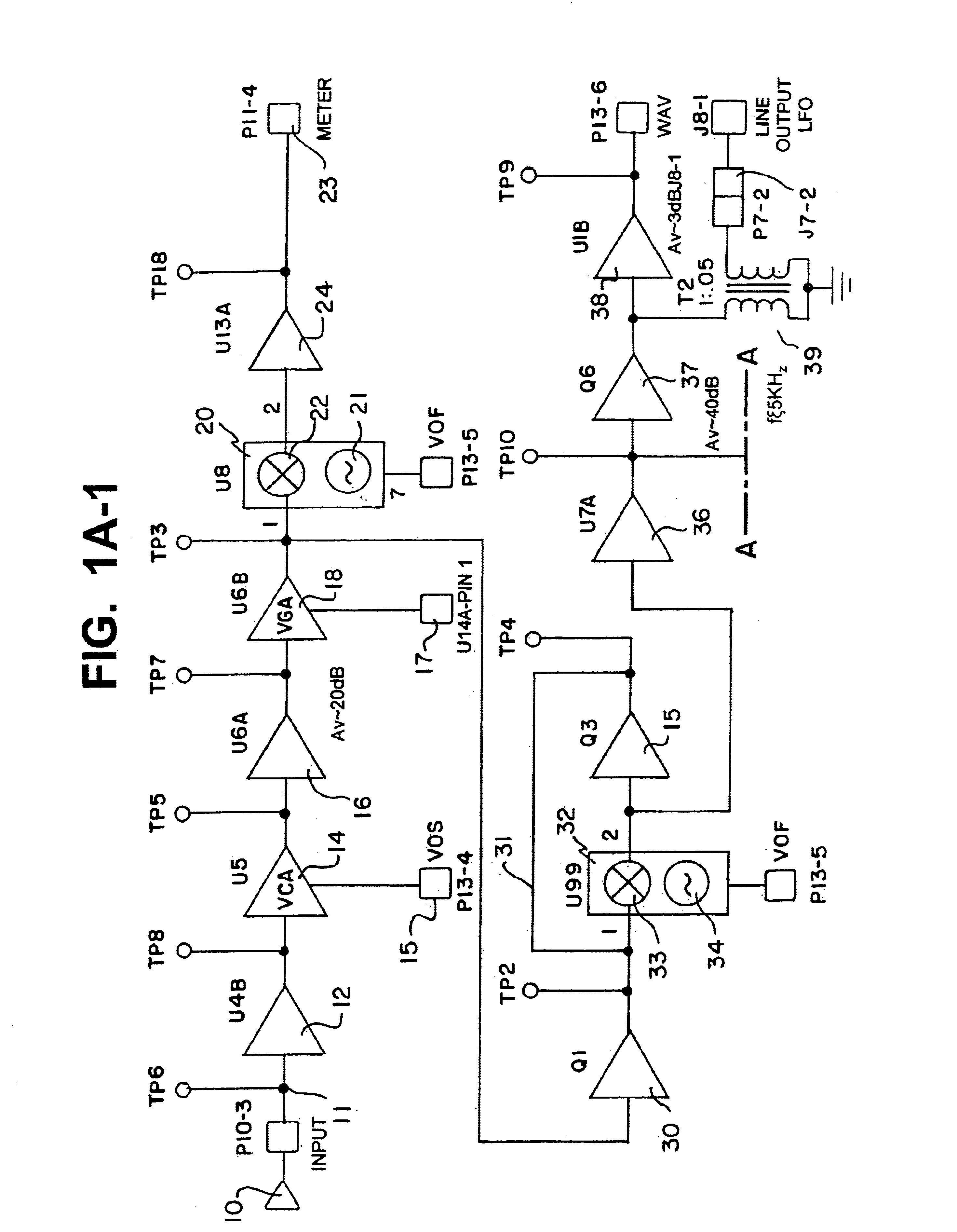
FIGS. 1A-1 and 1A-2 form an exemplary block diagram of the dual heterodyning circuit in accordance with the present invention which is located in the housing of the ultrasonic detector. In FIG. 1A-1, an input signal is applied from an ultrasonic transducer to a buffer amplifier 12 (U4B) at input 11 (P10). Typically, unity gain buffer 12 is used to maintain at a desi...


PUM


Abstract

A method and apparatus for detecting leaks and mechanical faults by way of an ultrasonic device. An output from a variable gain amplifier is supplied to a pair of heterodyning circuits, i.e., a dual heterodyning circuit. At each respective heterodyning circuit, the output signal from the variable gain amplifier is multiplied by a local oscillator that is internal to each circuit. The dual heterodyning circuit is used to provide an enhanced input transducer signal for spectral analysis. This permits the capture of low level frequency components for extraction during spectral analysis. The dual heterodyning circuit of the present invention to provide the enhanced spectrum to thereby permit an easy determination of whether the resonance is mechanical or electrical becomes clear. In addition, fault frequencies are also more easily discernable. In other words, the enhanced signal output provides a lower signal to noise ratio such that the ease with which frequency components are analyzed is increased.

Description

1. Field of the InventionThe invention generally relates to the field of ultrasonic generators and, more particularly, to a system and method for heterodyning an ultrasonic signal to produce lower frequency signals.2. Description of the Related ArtIt is well known that ultrasonic generators and detectors can be used to locate leaks or defects, e.g., in pipes. Such a system is shown in U.S. Pat. No. 3,978,915 to Harris. In that arrangement, ultrasonic generators are positioned in a chamber through which the pipes pass. At the ends of these pipes, exterior to the chamber, ultrasonic detectors are located. At the point where a leak occurs in the pipe or the pipe wall is thin, the ultrasonic energy will enter the pipe from the chamber and travel to the end of the pipe where the detector is located. The detector will receive an ultrasonic signal at the end of the pipe indicating the existence of the leak or weak spot in the pipe.By locating an ultrasonic generator in a closed chamber, a ...

Claims


Application Information

Patent Timeline
IPC IPC(8): G01M3/24G01N29/06G01N29/44G01N29/46
CPCG01M3/243G01N29/0609G01N29/44G01N29/46G01N2291/2634
Inventor GOODMAN, MARK A.BISHOP, WILLIAM
Owner U E SYST
Why Eureka
Try Eureka