
Linear solenoid control apparatus and method having increased responsiveness features

a solenoid control and responsiveness technology, applied in the direction of electric controllers, electric programme control, program control, etc., can solve the problems of affecting the actual responsiveness of the current control to the inductive load, affecting the original reflection speed, so as to achieve the effect of high degree of responsiveness

Inactive Publication Date: 2004-02-03
DENSO CORP
View PDF7 Cites 11 Cited by
  • Summary
  • Abstract
  • Description
  • Claims
  • Application Information

AI Technical Summary

Benefits of technology

In light of the foregoing problems, it is an object of the present invention to provide a pulse-width-modulated signal generating apparatus capable of changing the duty of a pulse-width-modulated signal with a high degree of responsiveness, without disturbing a pulse-width-modulated signal cycle.
It is also another object of the present invention to provide an apparatus that prevents a drop in control responsiveness in a current controller due to signal response delay produced by a detection-signal feedback or drive system.
In the above embodiment, pulse-width-modulated signal duty can be controlled at both the rise and the fall timings of the pulse-width-modulated signals. Therefore, the delay time after updating the pulse-width-modulated data until the pulse-width-modulated signals correspond to the duty after the updating becomes a maximum of the time of one-half of the pulse-width-modulated signal cycle, thereby improving control responsiveness.

Problems solved by technology

Therefore, the actual responsiveness that can be effected when controlling the current to the inductive load is limited.
As a result, the pulse-width-modulated signal cycle may be disturbed.
However, as a result of the suppression, a decline occurs even in the original reflection speed with respect to the duty of the pulse-width-modulated signals.
Thus, current control responsiveness is negatively affected.
For example, when the inductive load current is detected based on the voltage drop across a resistor provided in the conductive path of the inductive load, the detected current value fluctuates, and so stabilized control cannot be performed.
Because of this, considerable time is required until the current to the inductive load reaches the target current value and stabilizes, due to feedback delay, particularly delay due to the time constant of the lag circuit.
For this reason, the above-described apparatus cannot be utilized where responsiveness and control precision are demanded when updating the target current value, such as in a solenoid used in changing gears in an automatic transmission.
Even though the target current value is fixed, it becomes impossible to maintain the controlled current at a fixed value.
Consequently, a timing circuit is necessary to control the timing at which analog-to-digital conversion is performed in accordance with the rising edge and falling edge of the pulse-width-modulated signals, and the apparatus becomes complex in structure.
For this reason, in a current controller according to the prior art, time equal to a maximum of one pulse-width-modulated signals cycle is required until the duty computed in correspondence with the differential between the detected current value and the target current value is reflected in the driving of the switching element, and improvement in control responsiveness is limited.

Method used


Image

  • Linear solenoid control apparatus and method having increased responsiveness features
  • Linear solenoid control apparatus and method having increased responsiveness features
  • Linear solenoid control apparatus and method having increased responsiveness features

Examples


first embodiment

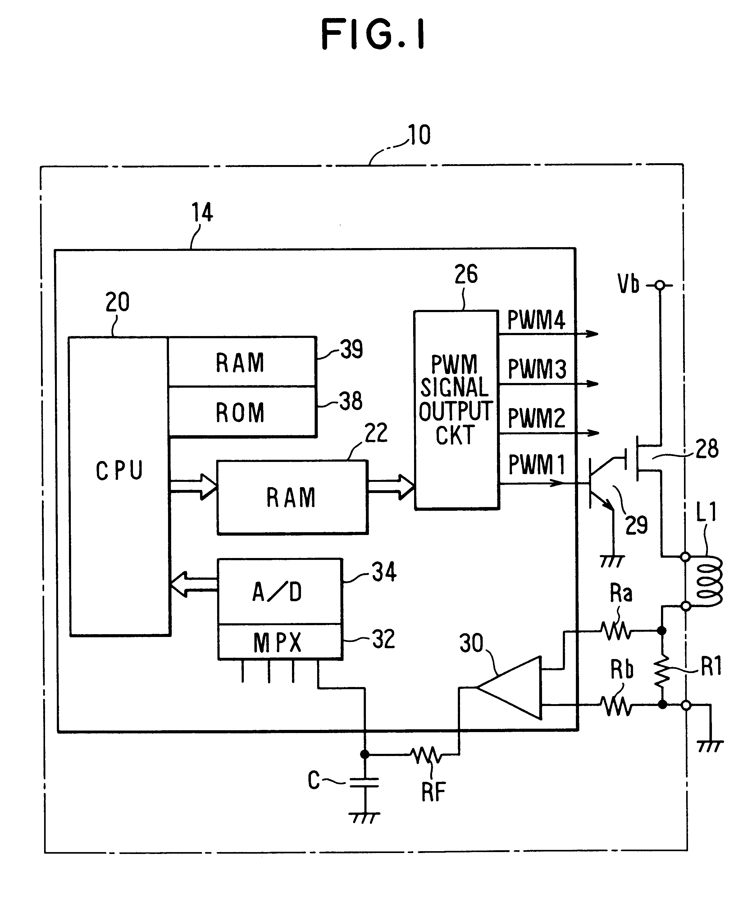
FIG. 1 is a block diagram depicting the structure of a conductivity controller (hereinafter termed simply "controller") 10 according to a first embodiment of the present invention for controlling linear solenoids in a vehicle-mounted electromagnetic-type solenoid or actuator.

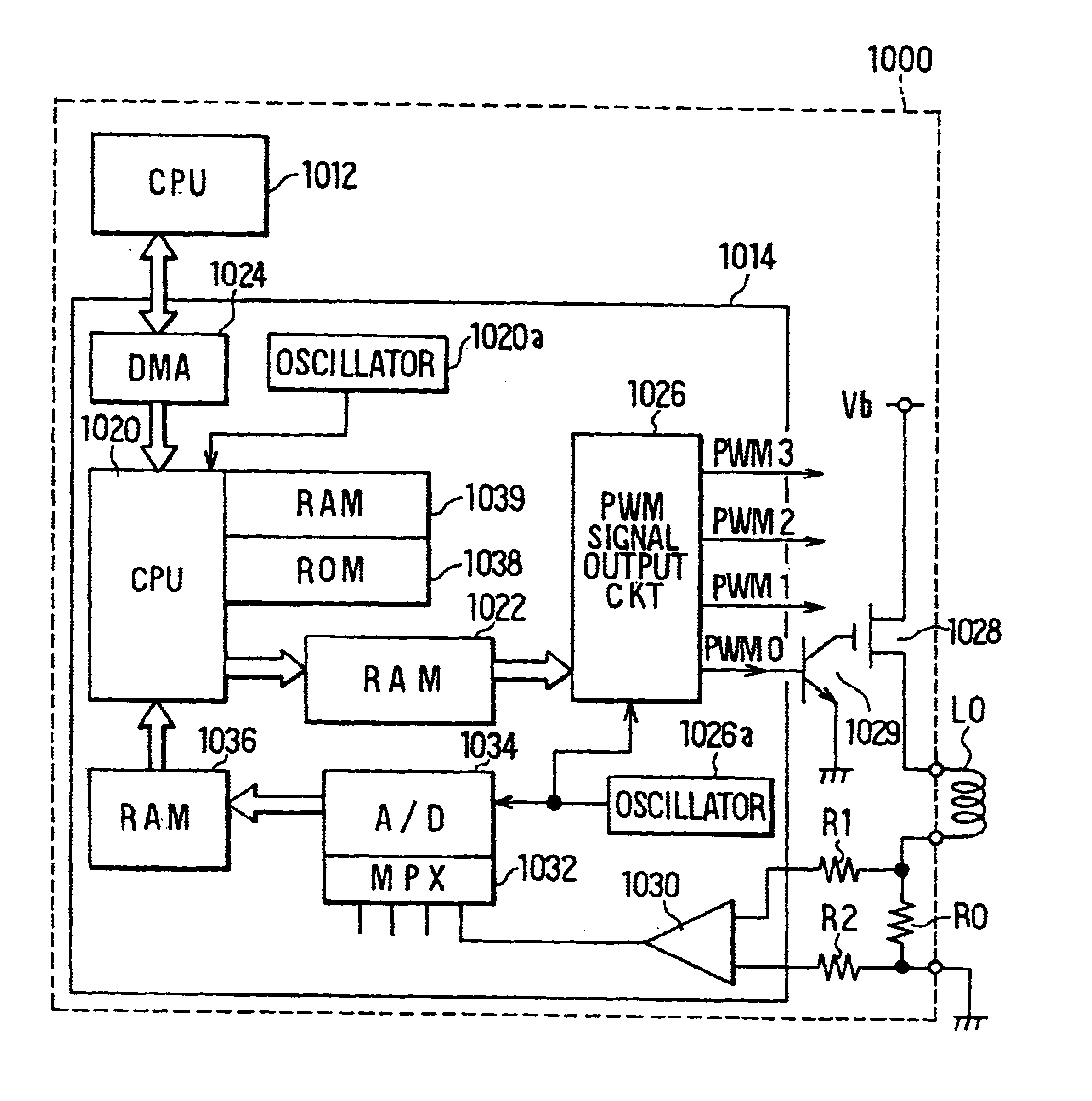
The controller 10 according to the first embodiment is an apparatus for individually controlling conduction of a plurality (in the embodiment, four) of linear solenoids L1-L4 (FIG. 1 shows only L1) of a vehicle internal combustion engine. The controller 10 includes a microprocessor for linear-solenoid control 14 for calculating a target current for the solenoids L1-L4 based on signals from various vehicle-mounted sensors (not illustrated), together with performing current feedback control of the respective linear solenoids L1-L4 according to the target current.

The microprocessor 14 includes a CPU 20 for performing processing related to control of the several linear solenoids L1-L4, calculating a duty for duty-dr...

second embodiment

A controller 10 according to a second embodiment differs from the controller according to the first embodiment solely in that the pulse-width-modulated signal-output processing executed every 1 .mu.sec with respect to the linear solenoids L1-L4 is executed as shown in FIG. 6. The processing shown in FIG. 6 also is achieved by a pulse-width-modulated signal-output processing portion within the output circuit 26. Operation of the processing portion will be described.

As shown in FIG. 6, in the processing of the second embodiment, at S310 it is determined whether the value of the counter CNT is "0." When the value of the counter CNT is not "0," execution proceeds directly to S335, but when the value of the counter CNT is "0," the time at which clocking of the half-cycle time of the signal PWMm by the counter CNT has started is considered to be obtained, and execution proceeds to S315.

At S315, the cycle data CYCL(m) of the signal PWMm is acquired from the RAM 22, and a value equal to one...

third embodiment

A controller 10 according to a third embodiment of the present invention differs from the above-described controllers of the first and second embodiments solely in that the pulse-width-modulated signal-output processing executed every 1 .mu.sec with respect to the linear solenoids L1-L4 by the signal output circuit 26 is executed as shown in FIG. 9. The processing shown in FIG. 9 also actually is achieved by a processing portion, which is logic circuitry disposed in each of the several linear solenoids L1-L4 within the signal output circuit 26.

As shown in FIG. 9, in the signal-output processing of the third embodiment, at S410 it is determined whether the value of the counter CNT is "0." Accordingly, when the value of the counter CNT is not "0," execution proceeds directly to S425. When the value of the counter CNT is "0," the time at which clocking of the half-cycle time of the signal PWMm by the counter CNT has started is considered to be obtained, and execution proceeds to S415.

A...


PUM


Abstract

A control system and method for controlling operation of a group of linear solenoids, which in turn control operation of an electrical load such as a solenoid or actuator, that exhibits increased responsiveness to a change in the target linear solenoid load current. A microcomputer cyclically generates and outputs pulse-width-modulated drive signals based on acquired drive data to establish clock periods. A switch connected between the microcomputer and the target load switchably connects the target load to a power source based on the drive data to selectively drive the target load. A feedback loop between the target load and the microcomputer provides actual target load drive data to the microcomputer, and the microcomputer adjusts the drive signals at a rate of not more than two times per cycle based on the actual drive data to converge the actual drive data to a calculated target load drive value. The present invention also provides an apparatus that prevents a drop in controller current control responsiveness due to signal response delay produced by feedback or the drive system. A converter converts input signals to digital values at a conversion cycle shorter than a cycle of the input signals. A data storage device sequentially stores digital values obtained from the converter, and a processor calculates a mean value to fetch the stored digital values for a cycle time of the input signals, and computes an arithmetic mean of the fetched digital values for target control purposes.

Description

The present application is related to, and claims priority from, Japanese Patent Application Nos. Hei. 10-110957 and Hei. 10-278747, the contents of which are incorporated herein by reference.BACKGROUND OF THE PRESENT INVENTION1. Technical FieldThe present invention relates generally to pulse-width modulated controls, and more particularly to controlling current to a linear solenoid in an electromagnetic-type solenoid or actuator to regulate the degree of opening of the solenoid or the amount of actuator displacement of a driven target.2. Related ArtLinear solenoids are provided in conventional solenoids or actuators to regulate actuation of the solenoid / actuator by regulating the amount of current flow to the solenoid / actuator. In turn, current flow to the linear solenoid is typically controlled by connecting the inductive load of the linear solenoid to a direct-current power source across a switching element, such as a conducting unit including a transistor, and then switching the...

Claims


Application Information

Patent Timeline
Patent Type & Authority Patents(United States)
IPC IPC(8): G05B19/19G05B19/33G05B11/28G05B11/01
CPCG05B11/28G05B19/33G05B2219/41333
Inventor HONDA, TAKAYOSHIKAMIYA, TAKAMICHI
Owner DENSO CORP
Learn More