
Composite articles reinforced with highly oriented microfibers

a technology of high-oriented microfibers and composite articles, applied in the field of composite materials, can solve the problems of composite articles with a relatively brittle matrix, many materials, such as metals, have the disadvantage of relatively high weight and density, and are unsuitable for marine applications, so as to increase the toughness of composite articles and add strength and stiffness to the elastomeric matrix material

Inactive Publication Date: 2003-10-07
3M INNOVATIVE PROPERTIES CO
View PDF109 Cites 102 Cited by
  • Summary
  • Abstract
  • Description
  • Claims
  • Application Information

AI Technical Summary

Benefits of technology

The matrix phase may be an elastomeric polymer in one embodiment, a thermoset polymer is another embodiment, a thermoplastic polymer in another embodiment, and a thermoplastic elastomeric polymer in yet another embodiment. A preferred matrix material in one embodiment is formed of thermoplastic, elastomeric syndiotactic polypropylene. One composite article according to the present invention is a brittle, rigid polymeric matrix having a microfibrous reinforcement phase. The microfibrous reinforcement phase can increase the toughness of the composite. The matrix phase may be either continuous or discontinuous. One discontinuous matrix phase includes numerous gas bubbles or pockets disposed within the matrix.
One article according to the present invention includes an elastomeric matrix having a stronger microfibrous reinforcement material within. The reinforcement can provide added strength and stiffness to the elastomeric matrix material. One strengthened composite material includes a transparent or translucent matrix material and a microfibrous reinforcement material having the same or similar refractive index as the matrix material, wherein the microfibrous reinforcement material is comprised of fibers small enough not to scatter light when essentially fully wetted by the matrix material. The resulting article may be strengthened by the microfibrous reinforcement material while appearing optically clear, or at least translucent. One composite article includes an elastomeric semi-syndiotactic polypropylene matrix phase, and a microfibrous reinforcement phase. Strengthened elastomeric composites may be used to form seals and gaskets.

Problems solved by technology

Some composites have a relatively brittle matrix and a relatively ductile or pliable reinforcement.
Many materials, such as metals, have the disadvantage relatively high weight and density.
Other materials, such as glass, may be inexpensive and lighter, but may wick moisture into the composite, which may make the composite unsuitable for some applications, such as marine applications.
In particular, long-term submersion in water may lead to significant water uptake and decomposition, including delamination in some applications.
The wicking may be caused by less than optimal adhesion between the fibers and the matrix phase, allowing moisture to be wicked in through the elongated voids formed between the fibers and the matrix.
Use of inexpensive polymers, such as olefins, would be advantageous with respect to cost and weight, but known olefin fibers that are strong enough to impart the required strength to the composite may not be capable of receiving stress from the matrix, because of the low surface energy nature of known olefin fiber surfaces.
These fibers have relatively large diameters and smooth surfaces, and are relatively expensive and are prepared by a gel spinning process followed by hot drawing.
When fiber reinforcements are added to a transparent matrix phase the resulting composite is typically opaque or cloudy.

Method used

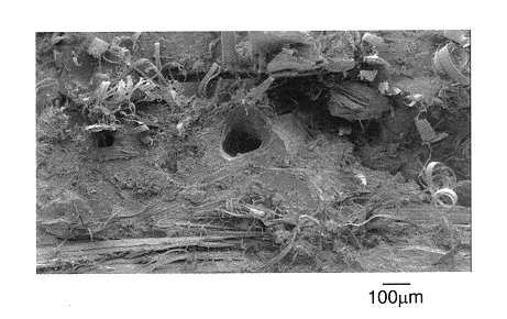
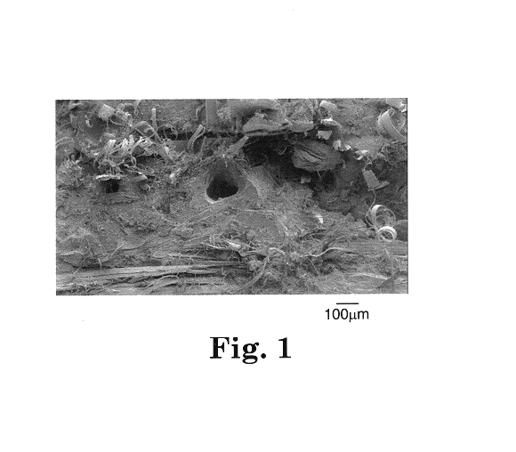
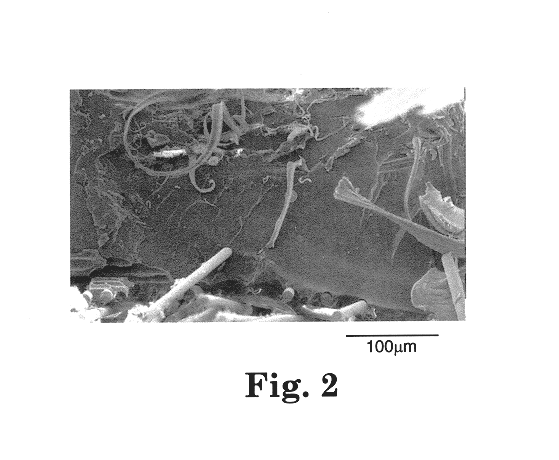

Image

  • Composite articles reinforced with highly oriented microfibers
  • Composite articles reinforced with highly oriented microfibers
  • Composite articles reinforced with highly oriented microfibers

Examples


examples 1-2

(Reinforced Elastomeric Polypropylene) and Comparative Example C1

Samples of semi-syndiotactic polypropylene were pressed into films ranging in thickness from 50.8 to 501 microns, using a Model C Carver Laboratory Press (Fred Carver Inc., Wabash, Ind.) with a 15.2.times.15.2 cm heated platten. The applied load was 6.895 Mpa, and the platten temperature either 121.degree. C. or 177.degree. C.

A microfibrillated web made by microfibrillating highly oriented polypropylene as described in Example 1 of U.S. Pat. No. 6,110,588 was sandwiched between two semi-syndiotactic polypropylene films having a thickness of 0.18 to 0.25 mm and pressed at 6.895 Mpa with the platen temperature at 121.degree. C. to a thickness of 0.30 to 0.38 mm. Visual inspection of the resulting reinforced syndiotactic polypropyene composite sheet revealed that complete wetting of the microfiber bundles was not achieved. Samples having a width of 0.635 cm and a length of about 7.6 cm were cut from the composite sheet, s...

examples 3-5

Comparative Example C2 (Microfiber Reinforced Thermoset Epoxy)

Microfiber reinforced thermoset samples were made using 1, 4 and 8 layers of cross-lapped microfibrillated web made by microfibrillating highly oriented polypropylene essentially as described in Example 1 of U.S. Pat. No. 6,110,588. The microfiber reinforcement web was measured to have a surface area of approximately 3.5 square meters per gram and a density of 0.10 g / cc. The microvoided highly oriented polypropylene film prior to fibrillation had a density of 0.7 g / cc.

ERL 4221 (a cycloaliphatic epoxy with a viscosity at room temperature of 400 cp, obtained from Union Carbide, Danbury, Conn.) was compounded with 2% by weight of triarylsulfonium hexafluoroantimonate (cationic catalyst R-23164, CAS#57840-38-7, in powder form, available from 3M, St. Paul, Minn.) in a stirred jacketed vessel at 100.degree. C. for fifteen minutes. The resulting catalyzed epoxy resin was poured over the microfibrillated web (10 cm.times.10 cm), ...

example 6-8

Comparative Example C3 (Microfiber Reinforced Thermoset Epoxy / Polyol)

Microfiber reinforced thermoset samples were made using one layer of 5.1 cm.times.5.1 cm squares of microfibrillated web (made by microfibrillating highly oriented polypropylene essentially as described in Example 1 of U.S. Pat. No. 6,110,588) with various amounts of thermoset resin. An epoxy / polyol thermoset resin was prepared essentially as in Example 3 by combining ERL 4221.TM. at 80% by weight with Tone 0201.TM. (a difunctional polycaprolactone polyol from Union Carbide) at 20% by weight. Triarylsulfonium hexafluoroantimonate (CD1010, a cationic photoinitiator, from Sartomer, Exton, Pa.), was used at 2% by weight. The microfiber reinforcement square was placed on release PET liner with silicone release. The epoxy / polyol composition was poured onto the mat and release liner was placed on top and then a roller was used to spread out the resin and wet the microfibers. A Model C Carver laboratory press was heated t...


PUM

PropertyMeasurementUnit
effective diameteraaaaaaaaaa
cross-sectional areaaaaaaaaaaa

Abstract

A composite formed of a polymer matrix phase having a reinforcement phase including polymeric microfibers. The microfibers are preferably formed of a highly oriented polymer, having a high modulus value and a large surface area. The large surface area can serve to tightly bind the microfibers to the polymer matrix phase. The microfibers can be provided as a fully- or partially-microfibrillated film, as a non-woven web of entangled microfibers, or as a pulp having free fibers. The microfibers can be embedded in, or impregnated with, a polymer or polymer precursor. Some composite articles are formed from thermoset resins cured about a highly oriented polypropylene microfiber reinforcement phase, providing a strong, tough, moisture resistant article. One composite includes a matrix and reinforcement formed of the same material type and having substantially equal refractive indices, allowing the composite to be optically clear.

Description

FIELD OF THE INVENTIONThe present invention is related generally to composite materials. More specifically, the present invention is related to composites comprised of polymer coated highly oriented microfibers and to composites having a polymeric bulk or matrix phase reinforced with highly oriented microfibers.BACKGROUND OF THE INVENTIONComposite materials are well known, and commonly consist of a continuous, bulk or matrix phase, and a discontinuous, dispersed, fiber, or reinforcement phase. Some composites have a relatively brittle matrix and a relatively ductile or pliable reinforcement. The relatively pliable reinforcement, which can be in the form of fibers, can serve to impart toughness to the composite. Specifically, the reinforcement may inhibit crack propagation as cracks through the brittle matrix are deflected and directed along the length of the fibers. Other composites have a relatively soft matrix and a relatively rigid or strong reinforcement phase, which can include...

Claims


Application Information

Patent Timeline
Patent Type & Authority Patents(United States)
IPC IPC(8): D01D5/00D01D5/42B29C43/20B29K105/10B32B5/26C08K7/02C08J5/04C08L101/00
CPCB32B5/26D01D5/423Y10T428/24355Y10T428/2913Y10T428/2973Y10T428/2904Y10T428/2924Y10T428/2929Y10T428/2976Y10T428/24994Y10T442/613B32B2367/00B32B2260/021B32B2310/0445B32B2310/14B32B2255/26B32B2305/20B32B2255/02B32B27/32B32B2323/10B32B2307/412B32B27/36B32B5/022B32B38/0008B32B2262/0253
Inventor PEREZ, MARIO A.SWAN, MICHAEL D.HOBBS, TERRY R.SIEDLE, ALLEN R.
Owner 3M INNOVATIVE PROPERTIES CO
Learn More